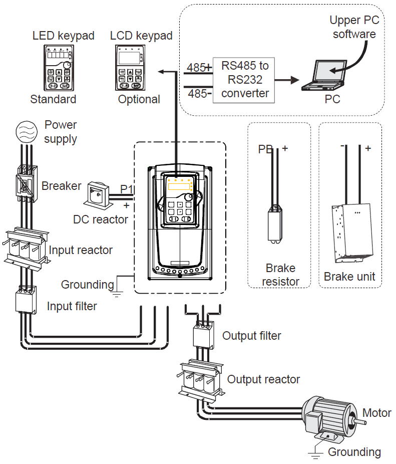
Below is the peripheral wiring of Goodrive35 series VFDs.
Note:
1. Built-in brake unit is included for 380 V 30 kW and below models;
2. P1 terminal is included for 380 V 37 kW and above models, which can be connected to external DC reactor directly;
3. P1 terminal is included for 660 V and above models, which can be connected to external DC reactor directly;
4. The brake units INVT's DBU series standard brake units. For details, see the DBU operation manual.
Pictures | Name | Descriptions |
| Cables | Device to transfer the electronic signals |
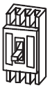
| Breaker | Prevent from electric shock and protect the power supply and the cables system from overcurrent when short circuits occur. (Please select the breaker with the function of reducing high order harmonic and the rated sensitive current to 1 VFD should be above 30mA). |
| Input reactor | This device is used to improve the power factor of the input side of the VFD and control thehigher harmonic current. The VFDs of 380 V (≥37 kW) and of 660 V have external DC reactors. |
| DC reactor | |
| Input filter | Control the electromagnetic interference generated from the VFD, please install close to the input terminal side of the VFD. Accessory that restricts the electromagnetic interference generated by the VFD and transmitted to the public grid through the power cable. Try to install the input filter near the input terminal side of the VFD. |
or
| Brake unit or brake resistors | Accessories used to consume the regenerative energy of the motor to reduce the deceleration time. VFDs of 380 V, 30 kW or lower need only to be configured with brake resistors, those of 380V, 37 kW or higher and 660 V series also need to be configured with brake units,. |
| Output filter | Control the interference from the output side of the VFD and please install close to the output terminals of the VFD. |
| Output reactor | Prolong the effective transmitting distance of the VFD to control the sudden high voltage when switching on/off the IGBT of the VFD. |