D.8.1 Selecting the brake components
When a VFD driving a high-inertia load decelerates or needs to decelerate abruptly, the motor runs in the power generation state and transmits the load-carrying energy to the DC circuit of the VFD, causing the bus voltage of the VFD to rise. If the bus voltage exceeds a specific value, the VFD reports an overvoltage fault. To prevent this from happening, you need to configure brake components.
| The design, installation, commissioning, and operation of the device must be performed by trained and qualified professionals. Follow all the "Warning" instructions during the operation. Otherwise, major physical injuries or property loss may be caused. Only qualified electricians are allowed to perform the wiring. Otherwise, damage to the VFD or brake components may be caused. Read the brake resistor or unit instructions carefully before connecting them to the VFD. Connect brake resistors only to the terminals PB and (+), and brake units only to the terminals (+) and (-). Do not connect them to other terminals. Otherwise, damage to the brake circuit and VFD and fire may be caused. |
| Connect the brake components to the VFD according to the wiring diagram. If the wiring is not properly performed, damage to the VFD or other devices may be caused. |


D.8.1.1 Brake units for AC 3PH 380 V (-15%)–440 V (+10%)
Goodrive350 series VFDs of 380 V, 37 kW or lower are equipped with built-in brake units, and those of 380 V, 45 kW or higher need to be configured with external brake units. Select brake resistors according to the specific requirements (such as the brake torque and brake usage requirements) on site.
Model | Brake unit model | Brake resistor value matched with 100% brake torque (Ω) | Dissipation power of brake resistor (kW) (10% brake) | Dissipated power of brake resistor (kW) (50% brake) | Dissipated power of brake resistor (kW) (80% brake) | Min allowed brake resistor (Ω) |
Built-in brake unit | 326 | 0.23 | 1.1 | 1.8 | 170 | |
GD35-2R2G-4-C1/D1/H1 | 222 | 0.33 | 1.7 | 2.6 | 130 | |
GD35-004G-4-C1/D1/H1/H2 | 122 | 0.6 | 3 | 4.8 | 80 | |
GD35-5R5G-4-C1/D1/H1/H2 | 89 | 0.75 | 4.1 | 6.6 | 60 | |
GD35-7R5G-4-C1/D1/H1/H2 | 65 | 1.1 | 5.6 | 9 | 47 | |
GD35-011G-4-C1/D1/H1/H2 | 44 | 1.7 | 8.3 | 13.2 | 31 | |
GD35-015G-4-C1/D1/H1/H2 | 32 | 2 | 11 | 18 | 23 | |
GD35-018G-4-C1/D1/H1/H2 | 27 | 3 | 14 | 22 | 19 | |
GD35-022G-4-C1/D1/H1/H2 | 22 | 3 | 17 | 26 | 17 | |
GD35-030G-4-C1/D1/H1/H2 | 17 | 5 | 23 | 36 | 17 | |
GD35-037G-4-C1/D1/H1 | DBU100H-060-4 | 13 | 6 | 28 | 44 | 11.7 |
GD35-045G-4-C1/D1/H1 | DBU100H-110-4 | 10 | 7 | 34 | 54 | 6.4 |
GD35-055G-4-C1/D1/H1 | 8 | 8 | 41 | 66 | ||
GD35-075G-4-C1/D1/H1 | 6.5 | 11 | 56 | 90 | ||
GD35-090G-4-C1/D1/H1 | DBU100H-160-4 | 5.4 | 14 | 68 | 108 | 4.4 |
GD35-110G-4-C1/D1/H1 | 4.5 | 17 | 83 | 132 | ||
GD35-132G-4-C1/D1/H1 | DBU100H-220-4 | 3.7 | 20 | 99 | 158 | 3.2 |
GD35-160G-4-C1/D1/H1 | DBU100H-320-4 | 3.1 | 24 | 120 | 192 | 2.2 |
GD35-185G-4-C1/D1/H1 | 2.8 | 28 | 139 | 222 | ||
GD35-200G-4-C1/D1/H1 | 2.5 | 30 | 150 | 240 | ||
GD35-220G-4-C1/D1/H1 | DBU100H-400-4 | 2.2 | 33 | 165 | 264 | 1.8 |
GD35-250G-4-C1/D1/H1 | 2.0 | 38 | 188 | 300 | ||
GD35-280G-4-C1/D1/H1 | Two DBU100H-320-4 | 3.6*2 | 21*2 | 105*2 | 168*2 | 2.2*2 |
GD35-315G-4-C1/D1/H1 | 3.2*2 | 24*2 | 118*2 | 189*2 |
Note:
1. Select the resistor and power of the brake unit according to the data our company provided.
2. The brake resistor may increase the brake torque of the VFD. The preceding table describes the resistance and power for 100% brake torque, 10% brake usage, 50% brake usage, and 80% brake usage. You can select the brake system based on the actual operation conditions.
3. When using an external brake unit, set the brake voltage class of the brake unit properly by referring to the manual of the dynamic brake unit. If the voltage class is set incorrectly, the VFD may not run properly.
| Do not use brake resistors whose resistance is lower than the specified minimum resistance. VFDs do not provide protection against overcurrent caused by resistors with low resistance. |
| In scenarios where brake is frequently implemented, that is, the brake usage is greater than 10%, you need to select a brake resistor with higher power as required by the operation conditions according to the preceding table. |


D.8.1.2 Brake units for AC 3PH 520 V (-15%)–690 V (+10%) brake unit
External brake units need to be configured for Goodrive350 series VFDs of 660 V. Select brake resistors according to the specific requirements (such as the brake torque and brake usage requirements) on site.
Model | Brake unit model | Brake resistor value matched with 100% brake torque (Ω) | Dissipation power of brake resistor (kW) (10% brake) | Dissipated power of brake resistor (kW) (50% brake) | Dissipated power of brake resistor (kW) (80% brake) | Min allowed brake resistor (Ω) |
GD35-022G-6-C1/D1/H1 | DBU100H-110-6 | 55 | 4 | 17 | 27 | 10.0 |
GD35-030G-6-C1/D1/H1 | 40.3 | 5 | 23 | 36 | ||
GD35-037G-6-C1/D1/H1 | 32.7 | 6 | 28 | 44 | ||
GD35-045G-6-C1/D1/H1 | 26.9 | 7 | 34 | 54 | ||
GD35-055G-6-C1/D1/H1 | 22.0 | 8 | 41 | 66 | ||
GD35-075G-6-C1/D1/H1 | 16.1 | 11 | 56 | 90 | ||
GD35-090G-6-C1/D1/H1 | 13.4 | 14 | 68 | 108 | ||
GD35-110G-6-C1/D1/H1 | 11.0 | 17 | 83 | 132 | ||
GD35-132G-6-C1/D1/H1 | DBU100H-160-6 | 9.2 | 20 | 99 | 158 | 6.9 |
GD35-160G-6-C1/D1/H1 | 7.6 | 24 | 120 | 192 | ||
GD35-185G-6-C1/D1/H1 | DBU100H-220-6 | 6.5 | 28 | 139 | 222 | 5.0 |
GD35-200G-6-C1/D1/H1 | 6.1 | 30 | 150 | 240 | ||
GD35-220G-6-C1/D1/H1 | 5.5 | 33 | 165 | 264 | ||
GD35-250G-6-C1/D1/H1 | DBU100H-320-6 | 4.8 | 38 | 188 | 300 | 3.4 |
GD35-280G-6-C1/D1/H1 | 4.3 | 42 | 210 | 336 | ||
GD35-315G-6-C1/D1/H1 | 3.8 | 47 | 236 | 378 | ||
GD35-350G-6-C1/D1/H1 | 3.5 | 53 | 263 | 420 | ||
GD35-400G-6-C1/D1/H1 | DBU100H-400-6 | 3.0 | 60 | 300 | 480 | 2.8 |
GD35-500G-6-C1/D1/H1 | Two DBU100H-320-6 | 4.8*2 | 38*2 | 188*2 | 300*2 | 3.4*2 |
GD35-560G-6-C1/D1/H1 | 4.3*2 | 42*2 | 210*2 | 336*2 | ||
GD35-630G-6-C1/D1/H1 | 3.8*2 | 47*2 | 236*2 | 378*2 |
Note:
1. Select brake resistors according to the resistance and power data provided by our company.
2. The brake resistor may increase the brake torque of the VFD. The preceding table describes the resistance and power for 100% brake torque, 10% brake usage, 50% brake usage, and 80% brake usage. You can select the brake system based on the actual operation conditions.
3. When using an external brake unit, set the brake voltage class of the brake unit properly by referring to the manual of the dynamic brake unit. If the voltage class is set incorrectly, the VFD may not run properly.
| Do not use brake resistors whose resistance is lower than the specified minimum resistance. VFDs do not provide protection against overcurrent caused by resistors with low resistance. |
| In scenarios where brake is frequently implemented, that is, the brake usage is greater than 10%, you need to select a brake resistor with higher power as required by the operation conditions according to the preceding table. |


D.8.2 Selecting the brake resistor cables
Brake resistor cables need to be shielded cables.
D.8.3 Installing the brake resistor
All resistors need to be installed in places with good cooling conditions.
| The materials near the brake resistor or brake unit must be non-flammable. The surface temperature of the resistor is high. Air flowing from the resistor is of hundreds of degrees Celsius. Prevent any materials from coming into contact with the resistor. |

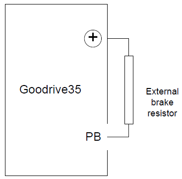
Installation of the brake resistor:
| VFDs of 380 V, 37 kW or lower need only external brake resistors. PB and (+) are the terminals for connecting brake resistors. |

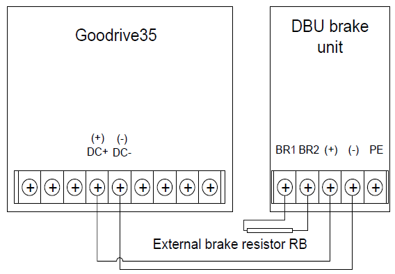
Installation of brake units:
| The VFDs of 380 V (≥37 kW) need external brake units. The VFDs of 660 V need external brake units. (+), (-) are the terminals for connecting brake units. The connection cables between the (+) and (-) terminals of a VFD and those of a brake unit must be shorter than 5 m, and the connection cables between the BR1 and BR2 terminals of a brake unit and the terminals of a brake resistor must be shorter than 10 m. |

The following figure shows the connection of one VFD to a dynamic brake unit.