The keypad is used to control Goodrive300 series VFDs, read the state data and adjust parameters. If you need to use the keypad in another place rather than on the VFD, use a network cable with a standard RJ45 crystal head as the extension cable.
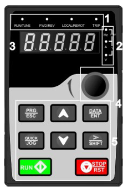
Figure 5-1 Keypad
Note:
1. The LED keypad is standard but the LCD keypad which can support various languages, parameters copy and 10-line displaying is optional.
2. It is necessary to use M3 screw or installation bracket to fix the external keypad. The installation bracket for VFDs of 380V 1.5–30kW and 500V 4–18.5kW is optional but it is standard for the VFDs of 380V 37–500kW, 500V 22–75kW and 660V.
No. | Name | Description | ||||
1 | State LED | RUN/TUNE | LED off means that the VFD is in the stopping state; LED blinking means the VFD is in the parameter autotune state; LED on means the VFD is in the running state. | |||
FWD/REV | FED/REV LED LED off means the VFD is in the forward rotation state; LED on means the VFD is in the reverse rotation state | |||||
LOCAL/REMOT | LED for keypad operation, terminals operation and remote communication control LED off means that the VFD is in the keypad operation state; LED blinking means the VFD is in the terminals operation state; LED on means the VFD is in the remote communication control state. | |||||
TRIP | LED for faults LED on when the VFD is in the fault state; LED off in normal state; LED blinking means the VFD is in the pre-alarm state. | |||||
2 | Unit LED | Mean the unit displayed currently | ||||
| Hz | Frequency unit | ||||
A | Current unit | |||||
V | Voltage unit | |||||
RPM | Rotating speed unit | |||||
% | Percentage | |||||
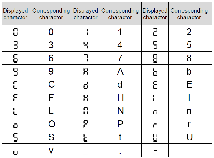
3 | Code displa- ying zone | 5-figure LED display displays various monitoring data and alarm code such as set frequency and output frequency.
| ||||
4 | Digital potent-iometer | Tuning frequency. Please refer to P08.41. | ||||
5 | Buttons |
| Progra-mming key | Enter or escape from the first level menu and remove the parameter quickly. | ||
| Entry key | Enter the menu step-by-step Confirm parameters. | ||||
| UP key | Increase data or function code progressively. | ||||
| DOWN key | Decrease data or function code progressively. | ||||
| Right-shift key | Move right to select the displaying parameter circularly in stopping and running mode. Select the parameter modifying digit during the parameter modification. | ||||
| Run key | This key is used to operate on the VFD in key operation mode. | ||||
| Stop/ Reset key | This key is used to stop in running state and it is limited by function code P07.04 This key is used to reset all control modes in the fault alarm state. | ||||
| Quick key | The function of this key is confirmed by function code P07.02. | ||||