10.4.1 Command code: 03H
03H (correspond to binary 0000 0011), read N words (Word)(Max. continuous reading is 16 words)
Command code 03H means that if the master read data form the VFD, the reading number depends on the "data number" in the command code. The Max. continuous reading number is 16 and the parameter address should be continuous. The byte length of every data is 2 (one word). The following command format is illustrated by hex (a number with "H" means hex) and one hex occupies one byte.
The command code is used to read the working stage of the VFD.
For example, read continuous 2 data content from0004H from the VFD with the address of 01H (read the content of data address of 0004H and 0005H), the frame structure is as below:
RTU master command message (from the master to the VFD)
START | T1-T2-T3-T4 (transmission time of 3.5 bytes) |
ADDR | 01H |
CMD | 03H |
High bit of the start bit | 00H |
Low bit of the start bit | 04H |
High bit of data number | 00H |
Low bit of data number | 02H |
Low bit of CRC | 85H |
High bit of CRC | CAH |
END | T1-T2-T3-T4 (transmission time of 3.5 bytes) |
T1-T2-T3-T4 between START and END is to provide at least the time of 3.5 bytes as the leisure time and distinguish two messages for the avoidance of taking two messages as one message.
ADDR = 01H means the command message is sent to the VFD with the address of 01H and ADDR occupies one byte
CMD=03H means the command message is sent to read data form the VFD and CMD occupies one byte
"Start address" means reading data form the address and it occupies 2 bytes with the fact that the high bit is in the front and the low bit is in the behind.
"Data number" means the reading data number with the unit of word. If the "start address’ is 0004H and the "data number" is 0002H, the data of 0004H and 0005H will be read.
CRC occupies 2 bytes with the fact that the high bit is in the front and the low bit is in the behind.
RTU slave response message (from the VFD to the master)
START | T1-T2-T3-T4 (transmission time of 3.5 bytes) |
ADDR | 01H |
CMD | 03H |
Byte number | 04H |
Data high bit of address 0004H | 13H |
Data low bit of address 0004H | 88H |
Data high bit of address 0005H | 00H |
Data low bit of address 0005H | 00H |
Low bit of CRC | 7EH |
High bit of CRC | 9DH |
END | T1-T2-T3-T4 (transmission time of 3.5 bytes) |
The meaning of the response is that:
ADDR = 01H means the command message is sent to the VFD with the address of 01H and ADDR occupies one byte
CMD=03H means the message is receiced from the VFD to the master for the response of reading command and CMD occupies one byte
"Byte number" means all byte number from the byte (excluding the byte) to CRC byte (excluding the byte). 04 means there are 4 byte of data from the "byte number" to "CRC CHK low bit", which are "digital address 0004H high bit", "digital address 0004H low bit", "digital address 0005H high bit" and "digital address 0005H low bit".
There are 2 bytes stored in one data with the fact that the high bit is in the front and the low bit is in the behind of the message, the data of data address 0004H is 1388H,and the data of data address 0005H is 0000H.
CRC occupies 2 bytes with the fact that the high bit is in the front and the low bit is in the behind.
10.4.2 Command code: 06H
06H (correspond to binary 0000 0110), write one word (Word)
The command means that the master write data to the VFD and one command can write one data other than multiple dates. The effect is to change the working mode of the VFD.
For example, write 5000 (1388H) to 0004H from the VFD with the address of 02H, the frame structure is as below:
RTU master command message (from the master to the VFD)
START | T1-T2-T3-T4 (transmission time of 3.5 bytes) |
ADDR | 02H |
CMD | 06H |
High bit of writing data address | 00H |
Low bit of writing data address | 04H |
Data content | 13H |
Data content | 88H |
Low bit of CRC | C5H |
High bit of CRC | 6EH |
END | T1-T2-T3-T4 (transmission time of 3.5 bytes) |
RTU slave response message (from the VFD to the master)
START | T1-T2-T3-T4 (transmission time of 3.5 bytes) |
ADDR | 02H |
CMD | 06H |
High bit of writing data address | 00H |
Low bit of writing data address | 04H |
High bit of data content | 13H |
Low bit of data content | 88H |
Low bit of CRC | C5H |
High bit of CRC | 6EH |
END | T1-T2-T3-T4 (transmission time of 3.5 bytes) |
Note: section 10.2 and 10.3 mainly describe the command format, and the detailed application will be mentioned in 10.8 with examples.
10.4.3 Command code 08H for diagnosis
Meaning of sub-function codes
Sub-function Code | Description |
0000 | Return to inquire information data |
For example: The inquiry information string is same as the response information string when the loop detection to address 01H of driver is carried out.
The RTU request command is:
START | T1-T2-T3-T4 (transmission time of 3.5 bytes) |
ADDR | 01H |
CMD | 08H |
High bit of sub-function code | 00H |
Low bit of sub-function code | 00H |
High bit of data content | 12H |
Low bit of data content | ABH |
Low bit of CRC | ADH |
High bit of CRC | 14H |
END | T1-T2-T3-T4 (transmission time of 3.5 bytes) |
The RTU response command is:
START | T1-T2-T3-T4 (transmission time of 3.5 bytes) |
ADDR | 01H |
CMD | 08H |
High bit of sub-function code | 00H |
Low bit of sub-function code | 00H |
High bit of data content | 12H |
Low bit of data content | ABH |
Low bit of CRC | ADH |
High bit of CRC | 14H |
END | T1-T2-T3-T4 (transmission time of 3.5 bytes) |
10.4.4 Command code: 10H, continuous writing
Command code 10H means that if the master writes data to the VFD, the data number depends on the "data number" in the command code. The Max. continuous reading number is 16.
For example, write 5000(1388H) to 0004H of the VFD whose slave address is 02H and 50(0032H) to 0005H, the frame structure is as below:
The RTU request command is:
START | T1-T2-T3-T4 (transmission time of 3.5 bytes) |
ADDR | 02H |
CMD | 10H |
High bit of write data | 00H |
Low bit of write data | 04H |
High bit of data number | 00H |
Low bit of data number | 02H |
Byte number | 04H |
High bit of data 0004H | 13H |
Low bit of data 0004H | 88H |
High bit of data 0005H | 00H |
Low bit of data 0005H | 32H |
Low bit of CRC | C5H |
High bit of CRC | 6EH |
END | T1-T2-T3-T4 (transmission time of 3.5 bytes) |
The RTU response command is:
START | T1-T2-T3-T4 (transmission time of 3.5 bytes) |
ADDR | 02H |
CMD | 10H |
High bit of write data | 00H |
Low bit of write data | 04H |
High bit of data number | 00H |
Low bit of data number | 02H |
Low bit of CRC | C5H |
High bit of CRC | 6EH |
END | T1-T2-T3-T4 (transmission time of 3.5 bytes) |
10.4.5 The definition of data address
The address definition of the communication data in this part is to control the running of the VFD and get the state information and related function parameters of the VFD.
10.4.5.1 Function code address representation rules
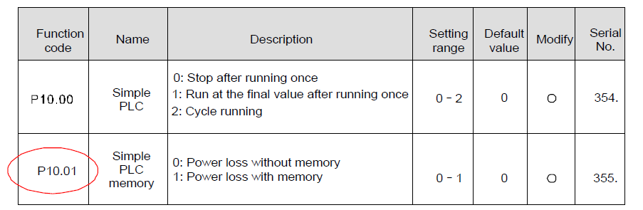
The parameter address occupies 2 bytes with the fact that the high bit is in the front and the low bit is in the behind. The range of high and low byte are: high byte—00–ffH; low byte—00–ffH. The high byte is the group number before the radix point of the function code and the low byte is the number after the radix point. But both the high byte and the low byte should be changed into hex. For example P05.06, the group number before the radix point of the function code is 05, then the high bit of the parameter is 05, the number after the radix point 06, then the low bit of the parameter is 06, then t he function code address is 0506H and the parameter address of P10.01 is 0A01H.
Note: P29 group is the factory parameter which cannot be read or changed. Some parameters cannot be changed when the VFD is in the running state and some parameters cannot be changed in any state. The setting range, unit and related instructions should be paid attention to when modifying the function code parameters.
Besides, EEPROM is stocked frequently, which may shorten the usage time of EEPROM. For users, some functions are not necessary to be stocked on the communication mode. The needs can be met on by changing the value in RAM. Changing the high bit of the function code form 0 to 1 can also realize the function. For example, the function code P00.07 is not stocked into EEPROM. Only by changing the value in RAM can set the address to 8007H. This address can only be used in writing RAM other than reading. If it is used to read, it is an invalid address.
10.4.5.2 The address instruction of other function in Modbus
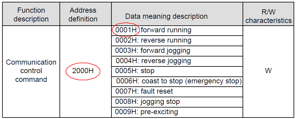
The master can operate on the parameters of the VFD as well as control the VFD, such as running or stopping and monitoring the working state of the VFD.
Below is the parameter list of other functions:
Function instruction | Address definition | Data meaning instruction | R/W characteristics |
Communication control command | 2000H | 0001H:forward running | R/W |
0002H:reverse running | |||
0003H:forward jogging | |||
0004H:reverse jogging | |||
0005H:stop | |||
0006H:coast to stop (emergency stop) | |||
0007H:fault reset | |||
0008H:jogging stop | |||
The address of communication setting | 2001H | Communication setting frequency(0–Fmax(unit: 0.01Hz)) | R/W |
2002H | PID given, range (0–1000, 1000 corresponds to100.0% ) | ||
2003H | PID feedback, range (0–1000, 1000 corresponds to100.0% ) | R/W | |
2004H | Torque setting value (-3000–3000, 1000 corresponds to the 100.0% of the rated current of the motor) | R/W | |
2005H | The upper limit frequency setting during forward rotation(0–Fmax(unit: 0.01Hz)) | R/W | |
2006H | The upper limit frequency setting during reverse rotation(0–Fmax(unit: 0.01Hz)) | R/W | |
2007H | The upper limit torque of electromotion torque (0–3000, 1000 corresponds to the 100.0% of the rated current of the motor) | R/W | |
2008H | The upper limit torque of braking torque (0–3000, 1000 corresponds to the 100.0% of the rated current of the motor) | R/W | |
2009H | Special control command word Bit0–1:=00: motor 1 =01: motor 2 =10: motor 3 =11: motor 4 Bit2:=1 torque control prohibit =0: torque control prohibit invalid Bit3:=1 power consumption clear =0:no power consumption clear Bit4:=1 pre-exciting enabling =0: pre-exciting disabling Bit5:=1 DC braking enabling =0: DC braking disabling | R/W | |
200AH | Virtual input terminal command , range: 0x000–0x1FF | R/W | |
200BH | Virtual output terminal command , range: 0x00–0x0F | R/W | |
200CH | Voltage setting value (special for V/F separation) (0–1000, 1000 corresponds to the 100.0%) | R/W | |
200DH | AO output setting 1 (-1000–1000, 1000 corresponds to 100.0%) | R/W | |
200EH | AO output setting 2 (-1000–1000, 1000 corresponds to 100.0%) | R/W | |
SW 1 of the VFD | 2100H | 0001H:forward running | R |
0002H:forward running | |||
0003H:stop | |||
0004H:fault | |||
0005H: POFF state | |||
0006H: pre-exciting state | |||
SW 2 of the VFD | 2101H | Bit0: =0: not ready for operation =1: ready for operation Bi1–2:=00:motor 1 =01:motor 2 =10:motor 3 =11:motor 4 Bit3: =0:asynchronous motor =1:synchronous motor Bit4: =0:pre-alarm without overload =1:overload pre-alarm Bit5– Bit6: =00: keypad control =01: terminal contorl =10: communication control | R |
Fault code of the VFD | 2102H | See the fault type instruction | R |
Identifying code of the VFD | 2103H | GD300-----0x010a | R |
Operation frequency | 3000H | 0–Fmax(unit: 0.01Hz) | R |
Setting freqency | 3001H | 0–Fmax(unit: 0.01Hz) | R |
Bus voltage | 3002H | 0.0–2000.0V (unit: 0.1V) | R |
Output voltage | 3003H | 0–1200V (unit: 1V) | R |
Output current | 3004H | 0.0–3000.0A (unit: 0.1A) | R |
Rotation speed | 3005H | 0–65535 (unit: 1RPM) | R |
Output power | 3006H | -300.0–300.0% (unit: 0.1%) | R |
Output torque | 3007H | -250.0–250.0% (unit: 0.1%) | R |
Close loop setting | 3008H | -100.0–100.0% (unit: 0.1%) | R |
Close loop feedback | 3009H | -100.0–100.0% (unit: 0.1%) | R |
Input IO state | 300AH | 000–1FF | R |
Output IO state | 300BH | 000–1FF | R |
Analog input 1 | 300CH | 0.00–10.00V (unit: 0.01V) | R |
Analog input 2 | 300DH | 0.00–10.00V (unit: 0.01V) | R |
Analog input 3 | 300EH | 0.00–10.00V (unit: 0.01V) | R |
Analog input 4 | 300FH | R | |
Read input of high-speed pulse 1 | 3010H | 0.00–50.00kHz (unit: 0.01Hz) | R |
Read input of high-speed pulse 2 | 3011H | R | |
Read the current stage of multi-step speed | 3012H | 0–15 | R |
External length | 3013H | 0–65535 | R |
External counting | 3014H | 0–65535 | R |
Torque setting | 3015H | -300.0–300.0% (unit: 0.1%) | R |
Identifying code of the VFD | 3016H | R | |
Fault code | 5000H | R |
R/W characteristics means the function is with read and write characteristics. For example, "communication control command" is writing chrematistics and control the VFD with writing command (06H). R characteristic can only read other than write and W characteristic can only write other than read.
Note:when operate on the VFD with the table above, it is necessary to enable some parameters. For example, the operation of running and stopping, it is necessary to set P00.01 to communication running command channel and set P00.02 to Modbus communication channel. And when operate on "PID given", it is necessary to set P09.00 to "Modbus communication setting".
The encoding rules for device codes (corresponds to identifying code 2103H of the VFD)
High 8 bit | Meaning | Low 8 bit | Meaning |
01 | GD | 0x08 | GD35 vector VFD |
0x09 | GD35-H1 vector VFD | ||
0x0a | GD300 vector VFD | ||
0x0b | GD100 simple vector VFD | ||
0x0c | GD200 universal VFD | ||
0x0d | GD10 mini VFD |
10.4.6 Fieldbus ratio values
The communication data is expressed by hex in actual application and there is no radix point in hex. For example, 50.12Hz cannot be expressed by hex so 50.12 can be magnified by 100 times into 5012, so hex 1394H can be used to express 50.12.
A non-integer can be timed by a multiple to get an integer and the integer can be called fieldbus ratio values.
The fieldbus ratio values are refered to the radix point of the setting range or default value in the function parameter list. If there are figures behind the radix point (n=1), then the fieldbus ratio value m is 10n. Take the table as the example:
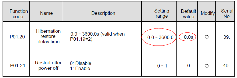
If there is one figure behind the radix point in the setting range or the default value, then the fieldbus ratio value is 10. if the data received by the upper monitor is 50, then the "hibernation restore delay time" is 5.0 (5.0=50÷10).
If Modbus communication is used to control the hibernation restore delay time as 5.0s. Firstly, 5.0 can be magnified by 10 times to integer 50 (32H) and then this data can be sent.
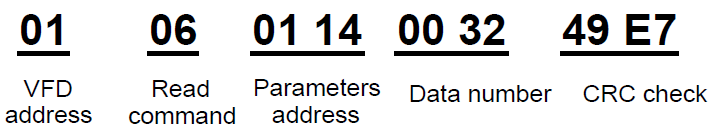
After the VFD receives the command, it will change 50 into 5 according to the fieldbus ratio value and then set the hibernation restore delay time as 5s.
Another example, after the upper monitor sends the command of reading the parameter of hibernation restore delay time ,if the response message of the VFD is as following:
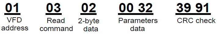
Because the parameter data is 0032H (50) and 50 divided by 10 is 5, then the hibernation restore delay time is 5s.
10.4.7 Fault message response
There may be fault in the communication control. For example, some parameter can only be read. If a writing message is sent, the VFD will return a fault response message.
The fault message is from the VFD to the master, its code and meaning is as below:
Code | Name | Meaning |
01H | Illegal command | The command from master cannot be executed. The reason maybe: 1. This command is only for new device; 2. Slave is in fault state and cannot execute it. |
02H | Illegal data address. | Some of the operation addresses are invalid or not allowed to access. Especially the combination of the register and the transmitting bytes are invalid. |
03H | Illegal value | When there are invalid data in the message framed received by slave. Note:This error code does not indicate the data value to write exceed the range, but indicate the message frame is an illegal frame. |
04H | Operation failed | The parameter setting in parameter writing is invalid. For example, the function input terminal cannot be set repeatedly. |
05H | Password error | The password written to the password check address is not same as the password set by P7.00. |
06H | Data frame error | In the frame message sent by the upper monitor, the length of the digital frame is incorrect or the counting of CRC check bit in RTU is different from the lower monitor. |
07H | Parameters only for reaf | It only happen in write command |
08H | Parameters cannot be changed during running | The modified parameter in the writing of the upper monitor cannot be modified during running. |
09H | Password protection | When the upper monitor is writing or reading and the user password is set without password unlocking, it will report that the system is locked. |
The slave uses functional code fields and fault addresses to indicate it is a normal response or some error occurs (named as objection response). For normal responses, the slave shows corresponding function codes, digital address or sub-function codes as the response. For objection responses, the slave returns a code which equals the normal code, but the first byte is logic 1.
For example: when the master sends a message to the slave, requiring it to read a group of address data of the VFD function codes, there will be following function codes:
0 0 0 0 0 0 1 1 (Hex 03H)
For normal responses, the slave responds the same codes, while for objection responses, it will return:
1 0 0 0 0 0 1 1 (Hex 83H)
Besides the function codes modification for the objection fault, the slave will respond a byte of abnormal code which defines the error reason.
When the master receives the response for the objection, in a typical processing, it will send the message again or modify the corresponding order.
For example, set the "running command channel" of the VFD (P00.01, parameter address is 0001H) with the address of 01H to 03, the command is as following:
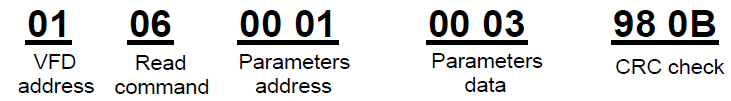
But the setting range of "running command channel" is 0–2, if it is set to 3, because the number is beyond the range, the VFD will return fault response message as below:
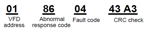
Abnormal response code 86H means the abnormal response to writing command 06H; the fault code is 04H. In the table above, its name is operation failed and its meaning is that the parameter setting in parameter writing is invalid. For example, the function input terminal cannot be set repeatedly.
10.4.8 Example of writing and reading
Refer to 10.4.1 and 10.4.2 for the command format.
10.4.8.1 Example of reading command 03H
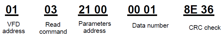
Read the state word 1 of the VFD with the address of 01H (refer to table 1). From the table 1, the parameter address of the state word 1 of the VFD is 2100H.
The command sent to the VFD:
If the response message is as below:
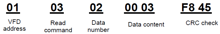
The data content is 0003H. From the table 1, the VFD stops.
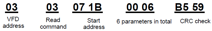
Watch "the current fault type" to "the previous 5 times fault type" of the VFD through commands, the corresponding function code is P07.27–P07.32 and corresponding parameter address is 071BH–0720H(there are 6 from 071BH).
The command sent to the VFD:
If the response message is as below:

See from the returned data, all fault types are 0023H (decimal 35) with the meaning of maladjustment (STo).
10.4.8.2 Example of writing command 06H
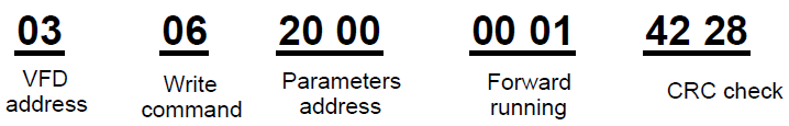
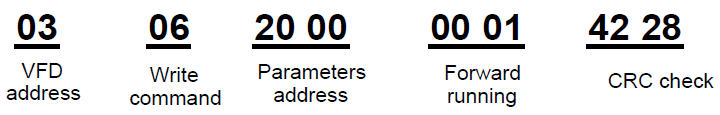
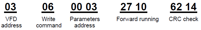
Make the VFD with the address of 03H to run forward. See table 1, the address of "communication control command" is 2000H and forward running is 0001. See the table below.
The command sent by the master:
If the operation is success, the response may be as below (the same with the command sent by the master):
Set the Max. Output frequency of the VFD with the address of 03H as100Hz.
Function code | Name | Detailed instruction of parameters | Setting range | Default value | Modify |
P00.03 | Max. output frequency | P00.04~600.00H (400.00Hz) | 100.00~600.00 | 50.00Hz | ◎ |
See the figures behind the radix point, the fieldbus ratio value of the Max. output frequency (P00.03) is 100. 100Hz timed by 100 is 10000 and the corresponding hex is 2710H.
The command sent by the master:
If the operation is successful, the response may be as below (the same with the command sent by the master):
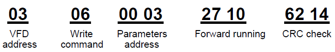
Note: the blank in the above command is for illustration. The blank cannot be added in the actual application unless the upper monitor can remove the blank by themselves.
10.4.8.3 Example of continous writing command 10H
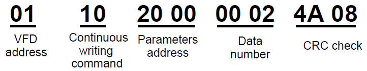
Example 1: make the VFD whose address is 01H run forward at 10Hz. Refer to the instruction of 2000H and 0001. Set the address of "communication setting frequency" is 2001H and 10Hz corresponds to 03E8H. See the table below.
Function instruction | Address definition | Data meaning instruction | R/W characteristics |
Communication control command | 2000H | 0001H:forward running | R/W |
0002H:reverse running | |||
0003H:forward jogging | |||
0004H:reverse jogging | |||
0005H:stop | |||
0006H:coast to stop (emergency stop) | |||
0007H:fault reset | |||
0008H:jogging stop | |||
The address of communication setting | 2001H | Communication setting frequency(0–Fmax(unit: 0.01Hz)) | R/W |
2002H | PID given, range (0–1000, 1000 corresponds to100.0% ) |
Set P00.01 to 2 and P00.06 to 8.
The command sent to the VFD:
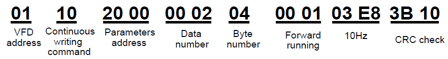
If the response message is as below:
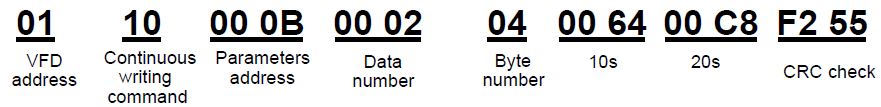
Example 2: set the ACC time of 01H VFD as 10s and the DEC time as 20s
P00.11 | ACC time 1 | ACC time means the time needed if the VFD speeds up from 0Hz to the Max. One (P00.03). DEC time means the time needed if the VFD speeds down from the Max. Output frequency to 0Hz (P00.03). Goodrive300 series VFDs define four groups of ACC/DEC time which can be selected by P05. The factory default ACC/DEC time of the VFD is the first group. Setting range of P00.11 and P00.12:0.0–3600.0s | Depend on model | ○ |
P00.12 | DEC time 1 | Depend on model | ○ |
The corresponding address of P00.11 is 000B, the ACC time of 10s corresponds to 0064H, and the DEC time of 20s corresponds to 00C8H.
The command sent to the VFD:
If the response message is as below:
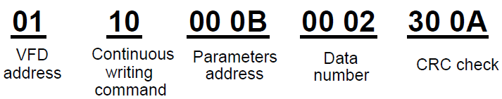
Note: The space between above commands is for instruction and there is no space between the commands during actual applications.
10.4.8.4 Modbus communication debugging instance
A PC is used as the host, an RS232-RS485 converter is used for signal conversion, and the PC serial port used by the converter is COM1 (a RS232 port). The upper computer commissioning software is the serial port commissioning assistant Commix, which can be downloaded from the Internet. Download a version that can automatically execute the CRC check function. The following figure shows the interface of Commix.
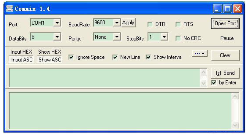
First, select COM1 for "serial port" and the baud rate should be set to the same value with P14.01. The data bit, check bit and stop bit must be consistent with the setup in P14.02. As RTU mode is used here, "HEX" should be selected. Check  to make the software add CRC automatically, and select CRC16 (ModbusRTU) with the starting byte being 1. Once enabled, CRC check will be added automatically, which removes the need to fill in CRC manually.
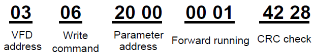
The commissioning command to set the VFD whose address is 03H to be forward running is as follows:
Note:
1. Set the address (P14.00) of the VFD to 03.
2. Set "Channel of running commands" (P00.01) to "Communication", and set "Communication channel of running commands" (P00.02) to the Modbus communication channel.
3. Click Send. If the line configuration and settings are correct, a response transmitted by the VFD will be received.