(1) PROFIBUS is an open international fieldbus standard that allows data exchange among various types of automation components. It is widely used in manufacturing automation, process automation and in other automation areas such as buildings, transportation, power, providing an effective solution for the realization of comprehensive automation and site-equipment intellectualization.
(2) PROFIBUS is composed of three compatible components, PROFIBUS -DP (Decentralized Periphery, distributed peripherals), PROFIBUS-PA (Process Automation), PROFIBUS-FMS (Fieldbus Message Specification). It is periodically exchange data with the VFD when using master-slave way. PRNV PROFIBUS-DP Adapter module only supports PROFIBUS-DP protocol.
(3) The physical transmission medium of bus is twisted-pair (in line with RS-485 standard), two-wire cable or fiber optic cable. Baud rate is from 9.6Kbit/s to 12Mbit/s. The maximum bus cable length is between 100 m and 1200 m, specific length depending on the selected transmission rate (see chapter Technical Data). Up to 31 nodes can be connected to the same PROFIBUS network when repeaters aren’t used. But, if use repeaters, up to 127 nodes can be connected to the same PROFIBUS network segment (including repeaters and master stations).
(4) In the process of PROFIBUS communication, tokens are assigned among main stations and master-slave transmission among master-slave stations. Supporting single-master or multi-master system, stations-programmable logic controller (PLC)-choose nodes to respond to the host instruction. Cycle master-from user data transmission and non-cyclic master-master station can also send commands to multiple nodes in the form of broadcast. In this case, the nodes do not need to send feedback signals to the host. In the PROFIBUS network, communication between nodes cannot be allowed.
(5) PROFIBUS protocol is described in detail in EN 50170 standard. To obtain more information about PROFIBUS, please refer to the above-mentioned EN 50170 standards.
A.2.1 Product naming rules
Fieldbus adapter naming rules, the product model:
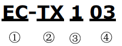
No. | Instruction | Meaning |
① | Product type | EC: extension card |
② | Card type | TX: communciation card |
③ | Technical | Odds such as 1,3,5,7 means the 1st, 2nd, 3rd, 4th technical version |
④ | Card difference | 03: PROFIBUS+Ethernet communication card 04: Ethernet+CAN communication card |
A.2.2 EC-TX-103 communication card
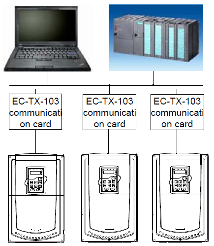
EC-TX-103 communication card is an optional device to VFD which makes VFD connected to PROFIBUS network. In PROFIBUS network, VFD is a subsidiary device. The following functions can be completed using EC-TX-103 communication card:
● Send control commands to VFD (start, stop, fault reset, etc.).
● Send speed or given torque signal to VFD.
● Read state and actual values from VFD.
● Modify VFD parameter.
Please refer to the description of function codes in Group P15 for the commands supported by the VFD. Below is the structure diagram of the connection between the VFD and PROFIBUS bus:
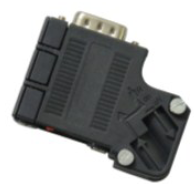
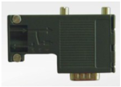
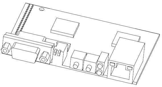
A.2.3 The appearance of EC-TX-103 communication card
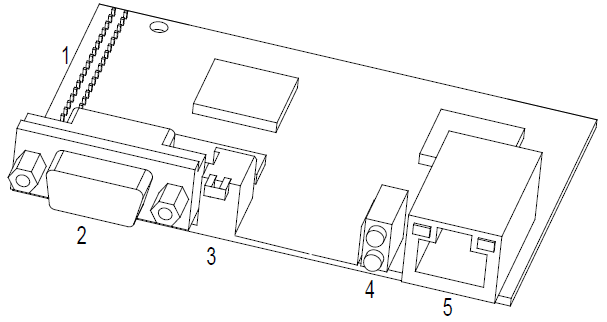
Outline diagram of EC-TX-103 communication card
1. Interface to the panel 2. Bus connector 3. Rotation node address selection switches 4. State display LEDs 5. Ethernet communication interface
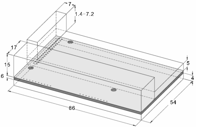
External dimensions of EC-TX-103 communication card (Unit: mm)
A.2.4 Compatible motor of EC-TX-103 communication card
EC-TX-103 communication card is compatible with the following products:
● Goodrive300 series devices and all blasters supporting PROFIBUS/CANOPEN extension
● Host station supporting PROFIBUS/CANOPEN-DP protocol
A.2.5 Delivery list
The package of EC-TX-103 communication card contains:
● EC-TX-103 communication card
● Three copper columns (M3x10)
● User’s manual
Please contact with the company or suppliers if there is something missing. Notice will not be given for the reason of product upgrades.
A.2.6 Installation of EC-TX-103 communication card
A.2.6.1 Mechanical installation of EC-TX-103 communication card
1. Installation ambient
● Ambient temperature: 0°C – +40°C
● Relative humidity: 5%–95%
● Other climate conditions: no drew, ice, rain, snow, hail air condition and the solar radiation is below 700W/m2, air pressure 70–106kPa
● Content of salt spray and corrosive gases : Pollution degree 2
● Dust and solid particles content: Pollution degree 2
● Vibration and shock: 5.9m/s2 (0.6g) on 9–200Hz sinusoidal vibration
2. Installation steps:
● Fix the three copper columns on the location holes with screws.
● Insert the module into the defined location carefully and fix it on the copper column with screw.
● Set the bus terminal switch of the module to the needed location.
3. Notes:
Disconnect the device from the power line before installation. Wait for at least three minutes to let the capacitors discharge. Cut off dangerous voltage from external control circuit to the unit output and input terminals.
Some electric components are sensitive to static charge. Do not touch the circuit board. If you have to operate on it, please wear the grounding wrist belt.
A.2.6.2 Electrical installation of EC-TX-103 communication card
1. Node selection
Node address is the only address of PROFIBUS on the bus. The address which is among 00–99 is shown with two figures and is selected by the spinning switch on the module. The left switch shows the first number and the right one show the second number.
Node address = 10 x the first digital value + the second digital value x 1
2. Bus terminals
There is a bus terminal in each heading and ending to avoid error during operation. The DIP switch on RPBA-01PCB is used to connect the bus terminals which can avoid the signal feedback from the bus cables. If the module is the first or last one in the internet, the bus terminal should be set as ON. Please disconnect EC-TX-103 communication card terminals when the PROFIBUS D-sub connector with internal terminals is in use.

A.2.6.3 Bus net connection of EC-TX-103 communication card
1. Bus communication interface
Transformation by double-shielded twisted pair copper cable is the most common way in PROFIBUS (conform to RS-485standard).
The basic characteristics of transformation technology:
● Net topology: Linear bus, there are bus resistor in two ends.
● Transforming speed: 9.6k bit/s–12M bit/s
● Medium: double-shielded twisted pair cables,the shield can be removed according to the environment (EMC).
● Station number: There are 32 stations in each segment (without relays) as to 127 stations (with relays)
● Contact pin: 9 frames D pin, the connector contact pins are as below:
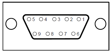
Contact pin of the connector | Instruction | |
1 | - | Unused |
2 | - | Unused |
3 | B-Line | Positive data(twisted pair cables 1) |
4 | RTS | Sending requirement |
5 | GND_BUS | Isolation ground |
6 | +5V BUS | Isolated 5V DC power supply |
7 | - | Unused |
8 | A-Line | Negative data(twisted pair cables 2) |
9 | - | Unused |
Housing | SHLD | PROFIBUS shielded cable |
+5V and GND_BUS are used in the fieldbus terminals. Some devices, such as light transceiver (RS485) may get external power supply form these pins.
RTS is used in some devices to determine the sending direction. Only A-Line wires, B-Line wires and shield are used in the normal application.
It is recommended to apply the standard DB9 connector of SIEMENS. If the communication baud rate is above 187.5kbps, please follow the connection rules of SIEMENS seriously.
Available |
Not available (with interference to the keypad wiring) |
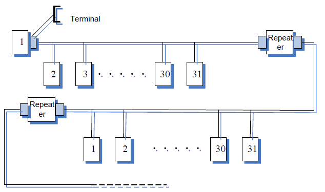
2. Repeater
Up to 32 stations can be connected to each segment (master station or subsidiary stations), the repeater have to be used when stations is more than 32. The repeaters in series are generally no more than 3.
Note: There is no repeater station address.
A.2.6.4 Transmission rate and maximum distance
Maximum length of cable depends on the transmission rate. The Table below shows the relationship between transmission rate and distance.
Transmission rate (kbps) | A-wire (m) | B-wire (m) |
9.6 | 1200 | 1200 |
19.2 | 1200 | 1200 |
93.75 | 1200 | 1200 |
187.5 | 1000 | 600 |
500 | 400 | 200 |
1500 | 200 | ----- |
12000 | 100 | ----- |
Transmission line parameters:
Transmission rate (kbps) | A-wire (m) | B-wire (m) |
Impedance (Ω) | 135–165 | 100–130 |
Capacitance per unit length(pF/m) | < 30 | < 60 |
Loop Resistance (Ω/km) | 110 | -------- |
Core wire diameter (mm) | 0.64 | > 0.53 |
Line-core cross-section (mm2) | > 0.34 | > 0.22 |
Besides shielding twisted-pair copper wires, PROFIBUS can also use optical fiber for transmission in an electromagnetic interference environment to increase the high-speed transmission distance there are two kinds of fiber optical conductors, one is low-cost plastic fiber conductor, used distance is less than 50 meters, the other is glass fiber conductor, and used distance is less than 1 kM.
A.2.6.5 PROFIBUS bus connection diagram
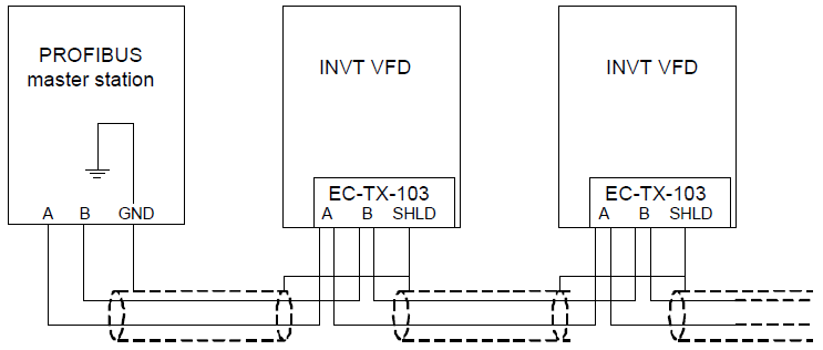
Above is "terminal" wiring diagram. Cable is a standard PROFIBUS cable consisting of a twisted pair and shielding layer. The shielded layer of PROFIBUS cable on all nodes is directly grounded. Users can choose the best grounding method according to the situation.
Note:
1. Make sure that signal lines do not twist when connecting all stations. Shielded cable should be used when system runs under high electromagnetic interface environment, which can improve electromagnetic compatibility (EMC).
2. If using shielded braided wire and shielding foil, both ends should be connected to ground. Using shielding area should be large enough to maintain a good conductivity. And data lines must be separated from high-voltage.
3. Stub line segment should not be used when transmission rate more than 500K bit/s, The plug is available on the market which connects directly to data input and output cable. Bus plug connection can be on or off at any time without interruption of data communications of other station.
A.2.7 System configuration
1. Master station and VFD should be configured so that the master station can communicate with the module after correctly installing EC-TX-103 communication card.
Each PROFIBUS subsidiary station on the PROFIBUS bus need to have "device description document" named GSD file which used to describe the characteristics of PROFIBUS -DP devices. The software we provided for the user includes VFD related GSD files (device data files) information, users can obtain type definition file (GSD) of master machines from local INVT agent.
Configuration parameters of EC-TX-103 communication card:
Parameter number | Parameter name | Optional setting | Factory setting | |
0 | Module type | Read only | PROFIBUS-DP | |
1 | Node address | 0–99 | 2 | |
2 | Baud rate setting | kbit/s | 0:9.6 | 6 |
1:19.2 | ||||
2:45.45 | ||||
3:93.75 | ||||
4:187.5 | ||||
5:500 | ||||
Mbit/s | 6:1.5 | |||
7:3 | ||||
8:6 | ||||
9:9 | ||||
10:12 | ||||
3 | PZD3 | 0–65535 | 0 | |
4 | PZD4 | The same as the above | 0 | |
… | …… | The same as the above | 0 | |
10 | PZD12 | The same as the above | 0 | |
2. Module type
This parameter shows communication module type detected by VFD; users cannot adjust this parameter. If this parameter is not defined, communication between the modules and VFD cannot be established.
3. Node address
In PROFIBUS network, each device corresponds to a unique node address, you can use the node address selection switch to define node address (switch isn’t at 0) and the parameter is only used to display the node address.
If node address selection switch is 0, this parameter can define node address. The user cannot adjust the parameter by themselves and the parameter is only used to display the node address.
4. GSD file
In PROFIBUS network, each PROFIBUS subsidiary station needs GSD file "device description document" which used to describe the characteristics of PROFIBUS-DP devices. GSD file contains all defined parameters, including baud rate, information length, amount of input/output data, meaning of diagnostic data.
A CD-ROM will be offered in which contains GSD file (extension name is .gsd) for fieldbus adapter. Users can copy GSD file to relevant subdirectory of configuration tools, please refer to relevant system configuration software instructions to know specific operations and PROFIBUS system configuration.
A.2.8 PROFIBUS-DP communication
1. PROFIBUS-DP
PROFIBUS-DP is a distributed I/O system, which enables master machine to use a large number of peripheral modules and field devices. Data transmission shows cycle: master machine read input information from subsidiary machine then give feedback signal. EC-TX-103 communication card supports PROFIBUS-DP protocol.
2. Service access point
PROFIBUS-DP has access to PROFIBUS data link layer (Layer 2) services through service access point SAP. Every independent SAP has clearly defined function. Please refer to relevant PROFIBUS user manual to know more about service access point information. PROFIDRIVE-Variable speed drive adopts PROFIBUS model or EN50170 standards (PROFIBUS protocol).
3. PROFIBUS-DP information frame data structures
PROFIBUS-DP bus mode allows rapid data exchange between master station and VFD. Adopting master-slave mode dealing with VFD access, VFD is always subsidiary station, and each has definite address. PROFIBUS periodic transmission messages use 16 words (16 bit) transmission, the structure shown in figure1.
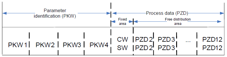
Parameters area:
PKW1-Parameter identification
PKW2-array index number
PKW3-parameter value 1
PKW4-parameter value 2
Process data:
CW-Control word (from master to slave)
SW-state word (from slave to master)
PZD-process data (decided by users)
(From master to slave output 【given value】, from slave to master input【actual value】)
PZD area (process data area):
PZD area of communication message is designed for control and monitor VFD. PZD from master and slave station is addressed in high priority; the priority of dealing with PZD is superior to that of PKW, and always sends current valid date from interface.
Control word (CW) and state word (SW):
Control word (CW) is a basic method of fieldbus system controlling VFD. It is sent by the fieldbus master station to VFD and the EC-TX-103 communication cards act as gateway. VFD responds according to the control word and gives feedbacks to master machine through state word (SW).
Given value: VFD can receive control information by several ways, these channels include: analog and digital input terminals, VFD control board and module communication (such as RS485, EC-TX-103 communication cards). In order to use PROFIBUS/CANOPEN control VFD, the communication module must be set to be VFD controller.
Actual value: Actual value is a 16-bit word, which contains converter operation information. Monitoring capabilities are defined by VFD parameter. The integer scaling of actual value is sent to master machine depending on selected function, please refer to VFD manual.
Note: VFD always check the control word (CW) and bytes of given value.
Mission message (From master station to VFD)
Control word (CW): The first word of PZD is control word (CW) of VFD. The definitions of CWs on the PWM rectifier regenerative part are different from those on the inverter part, and therefore two tables are used to describe the CWs.
Control word (CW) of Goodrive300 series
Bit | Name | Value | State/Description |
0–7 | COMMAND BYTE
| 1 | Forward running |
2 | Reverse running | ||
3 | Forward jogging | ||
4 | Reverse jogging | ||
5 | Decelerate to stop | ||
6 | Coast to stop (Emergency stop) | ||
7 | Fault reset | ||
8 | Jogging stop | ||
8 | WIRTE ENABLE | 1 | Write enable (mainly is PKW1-PKW4 ) |
9–10 | MOTOR GROUP SELECTION | 00 | MOTOR GROUP 1 SELECTION |
01 | MOTOR GROUP 2 SELECTION | ||
02 | MOTOR GROUP 3 SELECTION | ||
03 | MOTOR GROUP 4 SELECTION | ||
11 | TORQUE CONTROL SELECTION | 1 | Torque control enable |
0 | Torque control disable | ||
12 | ELECTRIC CONSUMPTION CLEAR | 1 | Electric consumption clear enable |
0 | Electric consumption clear disable | ||
13 | PRE-EXCIATION | 1 | Pre-exciation enable |
0 | Pre-exciation disable | ||
14 | DC BRAKE | 1 | DC braking enable |
0 | DC braking disable | ||
15 | HEARTBEAT REF | 1 | Heartbeat enable |
0 | Heartbeat disable |
Reference value (REF): From 2nd word to 12th of PZD task message is the main set value REF, main frequency set value is offered by main setting signal source. As PWM rectifier feedback part doesn’t have main frequency setting part, corresponding settings belong to reserved part, the following table describes inverter part settings for Goodrive300.
Bit | Name | Function selection |
PZD2 receiving | 0: Invalid 1: Set frequency(0–Fmax(unit:0.01Hz)) 2: Given PID, range (0–1000,1000 corresponds to 100.0%) 3: PID feedback, range (0–1000,1000 corresponds to 100.0%) 4: Torque set value (-3000–3000,1000 corresponds to 100.0% the rated current of the motor) 5: Set value of the forward rotation upper-limit frequency (0–Fmax unit:0.01Hz)) 6: Set value of the reversed rotation upper-limit frequency (0–Fmax(unit:0.01Hz)) 7: Electromotion torque upper limit (0–3000,1000 corresponds to 100.0%of the rated current of the motor) 8: Braking torque upper limit (0–2000,1000 corresponds to 100.0% of the rated current of the motor) 9: Virtual input terminals command, range:0x000–0x1FF 10: Virtual output terminals command, range:0x00–0x0F 11: Voltage setting value (special for V/F separation) (0–1000,1000 corresponds to 100.0% the rated voltage of the motor) 12: AO output set value 1 (-1000–1000, 1000 corresponds to 100.0%) 13: AO output set value 2 (-1000–1000, 1000 corresponds to 100.0%) | 0 |
PZD3 receiving | 0 | |
PZD4 receiving | 0 | |
PZD5 receiving | 0 | |
PZD6 receiving | 0 | |
PZD7 receiving | 0 | |
PZD8 receiving | 0 | |
PZD9 receiving | 0 | |
PZD10 receiving | 0 | |
PZD11 receiving | 0 | |
PZD12 receiving | 0 |
Response message (from the VFD to the master station)
State word (SW): The first word of PZD response message is state word (SW) of VFD, the definition of state word is as follows:
State word (SW) of Goodrive300 series
Bit | Name | Value | State/Description |
0–7 | RUN STATE BYTE | 1 | Forward running |
2 | Reverse running | ||
3 | The VFD stops | ||
4 | The VFD is in fault | ||
5 | The VFD is in POFF state | ||
6 | Pre-exciting state | ||
8 | DC VOLTAGE ESTABLISH | 1 | Running ready |
0 | The running preparation is not ready | ||
9–10 | MOTOR GROUP FEEDBACK | 0 | Motor 1 feedback |
1 | Motor 2 feedback | ||
2 | Motor 3 feedback | ||
3 | Motor 4 no feedback | ||
11 | MOTOR TYPE FEEDBACK | 1 | Synchronous motor |
0 | Asynchronous motor | ||
12 | OVERLOAD ALARM | 1 | Overload pre-alarm |
0 | Non-overload pre-alarm | ||
13 | RUN/STOP MODE | 0 | Keypad control |
1 | Terminal control | ||
14 | 2 | Communication control | |
3 | Reserved | ||
15 | HEARTBEAT FEEDBACK | 1 | Heartbeat feedback |
0 | No heartbeat feedback |
Actual value (ACT): From 2nd word to 12th of PZD task message is main set value ACT, main frequency set value is offered by main setting signal source.
Actual state value of Goodrive300 series
Bit | Name | Function selection |
PZD2 sending | 0: Invalid 1: Running frequency(×100, Hz) 2: Set frequency(×100, Hz) 3: Bus voltage (×10, V) 4: Output voltage (×1, V) 5: Output current (×10, A) 6: Output torque actual value (×10, %) 7: Output power actual value (×10, %) 8: Running rotating speed(×1, RPM) 9: Running linear speed (×1, m/s) 10: Ramp frequency reference 11:Fault code 12: AI1 value (×100, V) 13: AI2 value (×100, V) 14: AI3 value (×100, V) 15: PULSE frequency value (×100, kHz) 16:Terminals input state 17:Terminals output state 18: PID given (×100, %) 19: PID feedback (×100, %) 20: Motor rated torque 21: Control word | 0 |
PZD3 sending | 0 | |
PZD4 sending | 0 | |
PZD5 sending | 0 | |
PZD6 sending | 0 | |
PZD7 sending | 0 | |
PZD8 sending | 0 | |
PZD9 sending | 0 | |
PZD10 sending | 0 | |
PZD11 sending | 0 | |
PZD12 sending | 0 |
PKW area (parameter identification marks PKW1-value area). PKW area describes treatment of parameter identification interface, PKW interface is a mechanism which determine parameters transmission between two communication partners, such as reading and writing parameter values.
Structure of PKW area
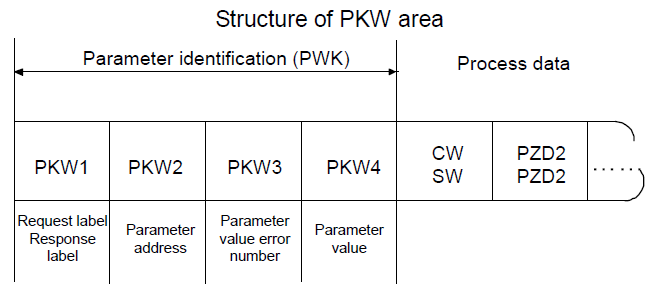
Parameter identification zone
In the process of periodic PROFIBUS-DP communication, PKW area is composed of four words (16 bit), each word is defined as follows:
The first word PKW1 (16 bit) | ||
Bit 15–00 | Task or response identification marks | 0–7 |
The second word PKW2 (16 bit) | ||
Bit 15–00 | Basic parameters address | 0–247 |
The third word PKW3 (16 bit) | ||
Bit 15–00 | Parameter value (high word) or return error code value | 00 |
The fourth word PKW4 (16 bit) | ||
Bit 15–00 | Parameter value (low word) | 0–65535 |
Note: If the master requests one parameter value, the value of PKW3 and PKW4 will not be valid.
Task requests and responses: When passing data to slave machine, master machine use request label while slave machine use response label to positive or negative confirmation. Table 5.5 and Table 5.6 list the request/response functional.
The definition of task logo PKW1 is as follows:
Request label (From master to slave) | Response label | ||
Request | Function | Positive confirmation | Negative confirmation |
0 | No task | 0 | - |
1 | Request parameter value | 1,2 | 3 |
2 | Modification parameter value (one word) [only change RAM] | 1 | 3 or 4 |
3 | Modification parameter value (double word) [only change RAM] | 2 | 3 or 4 |
4 | Modification parameter value (one word) [RAM and EEPROM are modified] | 1 | 3 or 4 |
5 | Modification parameter value (double word) [RAM and EEPROM are modified] | 2 | 3 or 4 |
Request label "2"-modification parameter value (one word) [only change RAM], "3"-modification parameter value (double word) [only change RAM], "5"-modification parameter value (double word) [RAM and EPROM are modified] not support currently.
Reponses logo PKW1 defines as below:
Response label (From slave to master) | |
Confirmation | Function |
0 | No response |
1 | Transmission parameter value ( one word) |
2 | Transmission parameter value ( two word) |
3 | Task cannot be executed and returns the following error number: 0: Illegal parameter number 1: Parameter values cannot be changed (read-only parameter) 2: Out of set value range 3: The sub-index number is not correct 4: Setting is not allowed (only reset) 5: Data type is invalid 6: The task could not be implemented due to operational state 7: Request isn’t supported. 8: Request can’t be completed due to communication error 9: Fault occurs when write operation to stationary store 10: Request fails due to timeout 11: Parameter cannot be assigned to PZD 12: Control word bit can’t be allocated 13: Other errors |
4 | No parameter change rights |
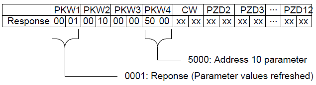
Example 1: Read parameter value. Read keypad set frequency value (the address of keypad set frequency is 10) which can be achieved by setting PKW1 as 1, PKW2 as 10, return value is in PKW4.
Request (From master to VFD):
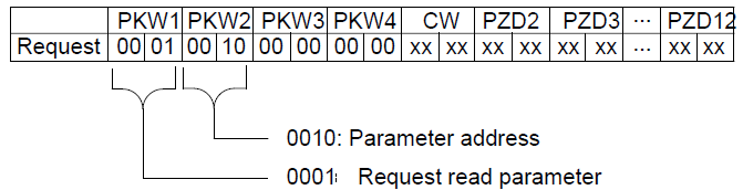
Response (From VFD to master)
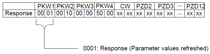
Example 2: Modify the parameter values (RAM and EEPROM are modified). Modify keypad settings frequency value (the address of keypad set frequency is 10) which can be achieved by setting PKW1 as 4; PKW2 as 10, modification value (50.00) is in PKW4.
Request (From master to VFD):
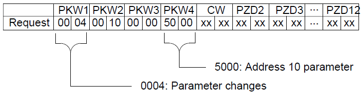
Response (From VFD to master)
Example for PZD:
Transmission of PZD area is achieved through VFD function code; please refer to relevant INVT VFD user manual to know relevant function code.
Example 1: Read process data of VFD
VFD parameter selects "8: Running rotation speed" as PZD3 to transmit which can be achieved by setting P15.14 as 8. This operation is mandatory until the parameter is instead of others.
Request (From master to VFD):
PKW1 | PKW2 | PKW3 | PKW4 | CW | PZD2 | PZD3 | … | PZD12 | |||||||||
Response | xx | xx | xx | xx | xx | xx | xx | xx | xx | xx | xx | xx | 00 | 0A | … | xx | xx |
Example 2: Write process data into VFD
VFD parameter selects "2": PID reference" from PZD3 which can be achieved by setting P15.03 as 2. In each request frame, parameters will use PZD3 to update until re-select a parameter.
Request (From master to converter):
PKW1 | PKW2 | PKW3 | PKW4 | CW | PZD2 | PZD3 | … | PZD12 | |||||||||
Response | xx | xx | xx | xx | xx | xx | xx | xx | xx | xx | xx | xx | 00 | 00 | … | xx | xx |
In each request frame contents of PZD3 are given by traction until re-select a parameter.
A.2.9 Fault information
EC-TX-103 communication card is equipped with 2 fault display LEDs as shown is figure below. The roles of these LEDs are as follows:
Fault display LEDs
LED No. | Name | Color | Function |
2 | Online | Green | ON-module online and data can be exchanged. OFF-module is not in "online" state. |
4 | Offline/Fault | Red | ON-module offline and data can’t be exchanged. OFF-module is not in "offline" state. 1. Flicker frequency 1Hz-configuration error: The length of user parameter data sets is different from that of network configuration process during module initialization process. 2. Flicker frequency 2Hz-user parameter data error: The length or content of user parameter data sets is different from that of network configuration process during module initialization process. 3. Flicker frequency 4Hz-PROFIBUS communication ASIC initialization error. 4. OFF-Diagnostic closed. |