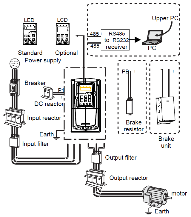
Below is the peripherial wiring of Goodrive300 series VFDs.
Note:
1. The VFD of 380V (≤30kW) are embedded with braking unit.
2. The VFDs of 380V (≥37kW) and of 660V have P1 terminal and are connected with external DC reators.
3. The VFD of 500V (≤18.5kW) are embedded with braking unit.
4. The VFDs of 500V (≥22kW) have P1 terminal and are connected with external DC reators.
5. The VFDs of 660V have P1 terminal and are connected with external DC reators.
6. The braking units apply standard braking units. Refer to the instruction of DBU for detailed information.
Pictures | Name | Descriptions |
| Cables | Device to transfer the electronic signals |
| Breaker | Prevent from electric shock and protect the power supply and the cables system from overcurrent when short circuits occur. (Please select the breaker with the function of reducing high order harmonic and the rated sensitive current to 1 VFD should be above 30mA). |
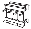
| Input reactor | This device is used to improve the power factor of the input side of the VFD and control thehigher harmonic current. The VFDs of 380V (≥37kW), 500V (≥22kW) and of 660V have external DC reactors. |
| DC reactor | |
| Input filter | Control the electromagnetic interference generated from the VFD, please install close to the input terminal side of the VFD. |
or
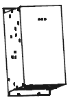
| Braking unit or resistors | Accessories used to consume the regenerative energy of the motor to reduce the deceleration time. VFDs of 380 V (≤30kW), and 500V (≤18.5kW) need only to be configured with brake resistors, those of 380V (≥37kW), 500V (≥22kW) and of 660V also need to be configured with brake units. |
| Output filter | Control the interference from the output side of the VFD and please install close to the output terminals of the VFD. |
| Output reactor | Prolong the effective transimiting distance of the VFD to control the sudden high voltage when switchiong on/off the inverter unit of the VFD. |