D.4.1 Power cables
Dimension the input power and motor cables according to local regulations.
• The input power and the motor cables must be able to carry the corresponding load currents.
• The cable must be rated for at least 70 °C maximum permissible temperature of the conductor in continuous use.
• The conductivity of the PE conductor must be equal to that of the phase conductor (same cross-sectional area).
• For details about the EMC requirements, see Appendix B "Technical data".
To meet the EMC requirements stipulated in the CE standards, you must use symmetrical shielded cables as motor cables (as shown in the following figure).
Four-core cables can be used as input cables, but symmetrical shielded cables are recommended. Compared with four-core cables, symmetrical shielded cables can reduce electromagnetic radiation as well as the current and loss of the motor cables.
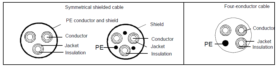
Note: If the conductivity of the shield layer of the motor cables cannot meet the requirements, separate PE conductors must be used.
To protect the conductors, the cross-sectional area of the shielded cables must be the same as that of the phase conductors if the cable and conductor are made of materials of the same type. This reduces grounding resistance, and thus improves impedance continuity.
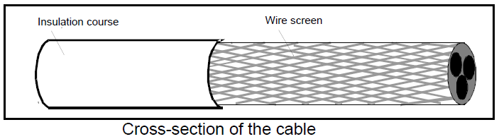
To effectively restrict the emission and conduction of radio frequency (RF) interference, the conductivity of the shielded cable must at least be 1/10 of the conductivity of the phase conductor. This requirement can be well met by a copper or aluminum shield layer. The following figure shows the minimum requirement on motor cables of a VFD. The cable must consist of a layer of spiral-shaped copper strips. The denser the shield layer is, the more effectively the electromagnetic interference is restricted.
D.4.2 Control cables
All analog control cables and cables used for frequency input must be shielded cables. Analog signal cables need to be double-shielded twisted-pair cables (as shown in figure a). Use one separate shielded twisted pair for each signal. Do not use the same ground wire for different analog signals.
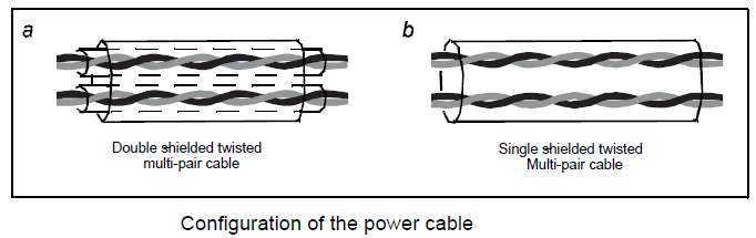
For low-voltage digital signals, double-shielded cables are recommended, but shielded or unshielded twisted pairs (as shown in figure b) also can be used. For frequency signals, however, only shielded cables can be used.
Relay cables need to be those with metal braided shield layers.
Keypads need to be connected by using network cables. In complicated electromagnetic environments, shielded network cables are recommended.
Note: Analog signals and digital signals cannot use the same cables, and their cables must be arranged separately.
Do not perform any voltage endurance or insulation resistance tests, such as high-voltage insulation tests or using a megameter to measure the insulation resistance, on the VFD or its components. Insulation and voltage endurance tests have been performed between the main circuit and chassis of each VFD before delivery. In addition, voltage limiting circuits that can automatically cut off the test voltage are configured inside the VFDs.
Note: Check the insulation conditions of the input power cable of a VFD according to the local regulations before connecting it.
D.4.2.1 The VFDs of AC 3PH 380V(-15%)–440V(+10%)
Recommended cable size (mm2) | Connecting cable size (mm2) | Terminal screw | Tightening torque (Nm) | |||||
RST UVW | PE | RST UVW | P1, (+) | PB (+),(-) | PE | |||
GD300-1R5G-4 | 2.5 | 2.5 | 2.5–6 | 2.5–6 | 2.5–6 | 2.5–6 | M4 | 1.2–1.5 |
GD300-2R2G-4 | 2.5 | 2.5 | 2.5–6 | 2.5–6 | 2.5–6 | 2.5–6 | M4 | 1.2–1.5 |
GD300-004G-4 | 2.5 | 2.5 | 2.5–6 | 2.5–6 | 2.5–6 | 2.5–6 | M4 | 1.2–1.5 |
GD300-5R5G-4 | 2.5 | 2.5 | 2.5–6 | 4–6 | 4–6 | 2.5–6 | M4 | 1.2–1.5 |
GD300-7R5G-4 | 4 | 4 | 4–16 | 4–16 | 4–16 | 4–16 | M5 | 2-–2.5 |
GD300-011G-4 | 6 | 6 | 6–16 | 6–16 | 6–16 | 6–16 | M5 | 2-–2.5 |
GD300-015G-4 | 10 | 10 | 10–25 | 10–25 | 10–25 | 6–25 | M5 | 2-–2.5 |
GD300-018G-4 | 16 | 16 | 16–25 | 16–25 | 16–25 | 10–25 | M5 | 2-–2.5 |
GD300-022G-4 | 16 | 16 | 16–25 | 16–25 | 16–25 | 10–25 | M6 | 4–6 |
GD300-030G-4 | 25 | 16 | 16–25 | 16–25 | 16–25 | 16–25 | M6 | 4–6 |
GD300-037G-4 | 25 | 16 | 25–50 | 25–50 | 25–50 | 16–50 | M8 | 9–11 |
GD300-045G-4 | 35 | 16 | 25–50 | 25–50 | 25–50 | 16–50 | M8 | 9–11 |
GD300-055G-4 | 50 | 25 | 50–95 | 50–95 | 50–95 | 25–50 | M8 | 9–11 |
GD300-075G-4 | 70 | 35 | 70–95 | 70–95 | 70–95 | 35–50 | M10 | 18–23 |
GD300-090G-4 | 95 | 50 | 95–150 | 95–150 | 95–150 | 50–150 | M10 | 18–23 |
GD300-110G-4 | 120 | 70 | 95–300 | 95–300 | 95–300 | 70–240 | M10 | 18–23 |
GD300-132G-4 | 185 | 95 | 95–300 | 95–300 | 95–300 | 95–240 | It is recommended to use wrench or sleeve because screw is used as terminal. | |
GD300-160G-4 | 240 | 120 | 95–300 | 95–300 | 95–300 | 120–240 | ||
GD300-200G-4 | 95×2P | 120 | 95×2P –150×2P | 95×2P –150×2P | 95×2P –150×2P | 120–240 | ||
GD300-220G-4 | 150×2P | 150 | 95×2P –150×2P | 95×2P –150×2P | 95×2P –150×2P | 150–240 | ||
GD300-250G-4 | 95×4P | 95×2P | 95×4P –150×4P | 95×4P –150×4P | 95×4P –150×4P | 95×2P –150×2P | ||
GD300-280G-4 | 95×4P | 95×2P | 95×4P –150×4P | 95×4P –150×4P | 95×4P –150×4P | 95×2P –150×2P | ||
GD300-315G-4 | 95×4P | 95×4P | 95×4P –150×4P | 95×4P –150×4P | 95×4P –150×4P | 95×2P –150×2P | ||
GD300-350G-4 | 95×4P | 95×4P | 95×4P –150×4P | 95×4P –150×4P | 95×4P –150×4P | 95×2P –150×2P | ||
GD300-400G-4 | 150×4P | 150×2P | 95×4P –150×4P | 95×4P –150×4P | 95×4P –150×4P | 95×2P –150×2P | ||
GD300-500G-4 | 150×4P | 150×2P | 95×4P –150×4P | 95×4P –150×4P | 95×4P –150×4P | 95×2P –150×2P | ||
Note:
1. Cables of the sizes recommended for the main circuit can be used in scenarios where the ambient temperature is lower than 40°C, the wiring distance is shorter than 100 m, and the current is the rated current.
2. The terminals P1, (+), and (-) are used to connect to DC reactors and brake accessories.
D.4.2.2 AC 3PH 380V(-10%)–550V(+10%)
Model | Recommended cable size (mm2) | Connecting cable size (mm2) | Terminal screw | Tightening torque (Nm) | ||||
RST UVW | PE | RST UVW | P1, (+) | PB (+),(-) | PE | |||
GD300-004G-5 | 2.5 | 2.5 | 2.5–6 | 2.5–6 | 2.5–6 | 2.5–6 | M5 | 2-–2.5 |
GD300-5R5G-5 | 2.5 | 2.5 | 2.5–6 | 2.5–6 | 2.5–6 | 2.5–6 | M5 | 2-–2.5 |
GD300-7R5G-5 | 2.5 | 2.5 | 2.5–6 | 4–6 | 4–6 | 2.5–6 | M5 | 2-–2.5 |
GD300-011G-5 | 4 | 4 | 4–16 | 4–16 | 4–16 | 4–16 | M5 | 2-–2.5 |
GD300-015G-5 | 6 | 6 | 6–16 | 6–16 | 6–16 | 6–16 | M5 | 2-–2.5 |
GD300-018G-5 | 10 | 10 | 10–16 | 10–16 | 10–16 | 10–16 | M5 | 2-–2.5 |
GD300-022G-5 | 16 | 16 | 16–50 | 16–50 | 16–50 | 16–50 | M8 | 9–11 |
GD300-030G-5 | 16 | 16 | 16–50 | 16–50 | 16–50 | 16–50 | M8 | 9–11 |
GD300-037G-5 | 25 | 16 | 25–50 | 25–50 | 25–50 | 16–50 | M8 | 9–11 |
GD300-045G-5 | 25 | 16 | 25–50 | 25–50 | 25–50 | 16–50 | M8 | 9–11 |
GD300-055G-5 | 35 | 16 | 35–50 | 35–50 | 35–50 | 16–50 | M8 | 9–11 |
GD300-075G-5 | 50 | 25 | 50–95 | 50–95 | 50–95 | 25–95 | M10 | 18–23 |
Note:
1. Cables of the sizes recommended for the main circuit can be used in scenarios where the ambient temperature is lower than 40°C, the wiring distance is shorter than 100 m, and the current is the rated current.
2. The terminals P1, (+), and (-) are used to connect to DC reactors and brake accessories.
D.4.2.3 The VFDs of AC 3PH 520V(-15%)–690V(+10%)
Model | Recommended cable size (mm2) | Connecting cable size (mm2) | Terminal screw | Tightening torque (Nm) | ||||
RST UVW | PE | RST UVW | P1,(+) | PB (+),(-) | PE | |||
GD300-022G-6 | 10 | 10 | 10–16 | 6–16 | 6–10 | 6–16 | M8 | 9–11 |
GD300-030G-6 | 10 | 10 | 10–16 | 6–16 | 6–10 | 6–16 | M8 | 9–11 |
GD300-037G-6 | 16 | 16 | 16–25 | 16–25 | 6–10 | 10–16 | M8 | 9–11 |
GD300-045G-6 | 16 | 16 | 10–16 | 16–35 | 10–16 | 10–16 | M8 | 9–11 |
GD300-055G-6 | 25 | 16 | 16–25 | 16–35 | 16–25 | 16–25 | M10 | 18–23 |
GD300-075G-6 | 35 | 16 | 25–50 | 25–50 | 25–50 | 16–25 | M10 | 18–23 |
GD300-090G-6 | 35 | 16 | 25–50 | 25–50 | 25–50 | 16–25 | M10 | 18–23 |
GD300-110G-6 | 50 | 25 | 35–95 | 50–95 | 25–95 | 25 | M10 | 18–23 |
GD300-132G-6 | 70 | 35 | 70–95 | 35–95 | 50–75 | 25–35 | M10 | 18–23 |
GD300-160G-6 | 95 | 50 | 35–95 | 35–150 | 25–70 | 50–150 | It is recommended to use wrench or sleeve because screw is used as terminal. | |
GD300-185G-6 | 95 | 50 | 35–95 | 35–150 | 25–70 | 50–150 | ||
GD300-200G-6 | 120 | 70 | 95–300 | 70–300 | 35–300 | 70–240 | ||
GD300-220G-6 | 185 | 95 | 95–300 | 70–300 | 35–300 | 95–240 | ||
GD300-250G-6 | 185 | 95 | 95–300 | 70–300 | 35–300 | 95–240 | ||
GD300-280G-6 | 240 | 120 | 95–300 | 95–300 | 70–300 | 120–240 | ||
GD300-315G-6 | 95×2P | 95 | 95–150 | 70–150 | 70–150 | 35–95 | ||
GD300-350G-6 | 95×2P | 95 | 95–150 | 70–150 | 70–150 | 35–95 | ||
GD300-400G-6 | 150×2P | 150 | 95–150 | 70–150 | 70–150 | 50–150 | ||
GD300-500G-6 | 95×4P | 95×2P | 95–150 | 70–150 | 70–150 | 70–150 | ||
GD300-560G-6 | 95×4P | 95×4P | 95–150 | 70–150 | 70–150 | 70–150 | ||
GD300-630G-6 | 150×4P | 150×2P | 95–150 | 70–150 | 70–150 | 70–150 | ||
Note:
1. Cables of the sizes recommended for the main circuit can be used in scenarios where the ambient temperature is lower than 40°C, the wiring distance is shorter than 100 m, and the current is the rated current.
2. The terminals P1, (+), and (-) are used to connect to DC reactors and brake accessories.
D.4.3 Routing the cables
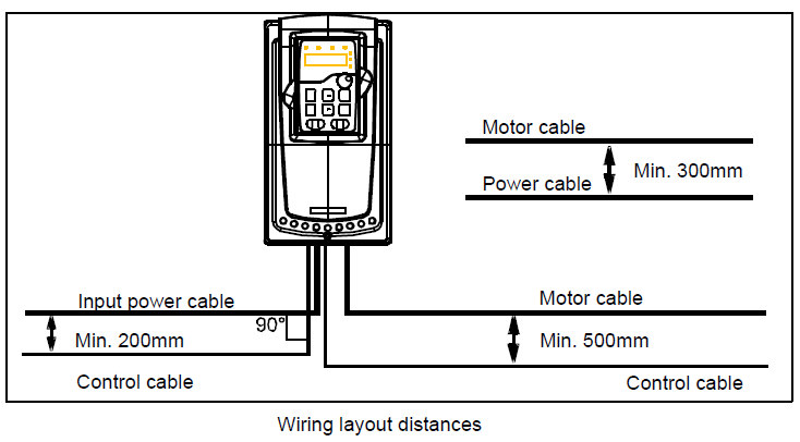
Route the motor cable away from other cable routes. Motor cables of several drives can be run in parallel installed next to each other. It is recommended that the motor cable, input power cable and control cables are installed on separate trays. Avoid long parallel runs of motor cables with other cables to decrease electromagnetic interference caused by the rapid changes in the drive output voltage.
Where control cables must cross power cables make sure that they are arranged at an angle as near to 90 degrees as possible.
The cable trays must have good electrical bonding to each other and to the grounding electrodes. Aluminum tray systems can be used to improve local equalizing of potential.
A figure of the cable routing is shown below.
D.4.4 Insulation checking
Check the insulation of the motor and motor cable as follows:
1. Check that the motor cable is connected to the motor and disconnected from the drive output terminals U, V and W.
2. Measure the insulation resistance between each phase conductor and the Protective Earth conductor using a measuring voltage of 500 V DC. For the insulation resistance of other motors, please consult the manufacturer’s instructions.
Note: Moisture inside the motor casing will reduce the insulation resistance. If moisture is suspected, dry the motor and repeat the measurement.