1.4.1 Delivery and installation
| ² Install the VFD on fire-retardant material and keep the VFD away from combustible materials. ² Connect the optional braking parts (braking resistors, braking units or feedback units) according to the wiring diagram. ² Do not operate on a damaged or incomplete VFD. ² Do not touch the VFD with wet items or body parts; otherwise, electric shock may occur. |

Note:
² Select appropriate tools for delivery and installation to ensure a safe and proper running of the VFD and avoid physical injury or death. To ensure physical safety, the installation staff should take mechanical protective measures like wearing safety shoes and working uniforms
² Protect the VFD against physical shock or vibration during delivery and installation.
² Do not carry the VFD by its front cover only as the cover may fall off.
² The installation site must be away from children and other public places.
² When the installation site altitude exceeds 1000m, derate by 1% for every increase of 100m; when the installation site altitude exceeds 3000m, consult local INVT dealer or office.
² Use the VFD in proper environment. (For details, see "Installation environment".)
² Prevent the screws, cables and other conductive parts from falling into the VFD.
² As leakage current of the VFD during running may exceed 3.5mA, ground properly and ensure the grounding resistance is less than 10Ω. The conductivity of PE grounding conductor is the same as that of the phase conductor (with the same cross sectional area).
² R, S and T are the power input terminals, and U, V and W are output motor terminals. Connect the input power cables and motor cables properly; otherwise, damage to the VFD may occur.
1.4.2 Commissioning and running
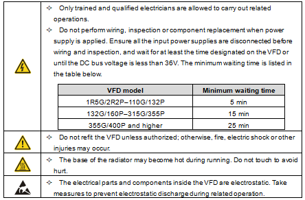
| ² Disconnect all power sources applied to the VFD before terminal wiring, and wait for at least the time designated on the VFD after disconnecting the power sources. ² High voltage presents inside the VFD during running. Do not carry out any operation on the VFD during running except for keypad setup. For products at voltage levels of 5 or 6, the control terminals form extra-low voltage circuits. Therefore, you need to prevent the control terminals from connecting to accessible terminals of other devices. ² The VFD may start up by itself when P01.21=1. Do not get close to the VFD and motor. ² The VFD cannot be used as "Emergency-stop device". ² The VFD cannot act as an emergency brake for the motor; it is a must to install mechanical brake device. ² During driving a permanent magnet SM, besides above-mentioned items, the following work must be done before installation and maintenance: a) Disconnect all the input power sources including main power and control power. b) Ensure the permanent-magnet SM has been stopped, and the voltage on output end of the VFD is lower than 36V. c) After the permanent-magnet SM is stopped, wait for at least the time designated on the VFD, and ensure the voltage between + and - is lower than 36V. d) During operation, it is a must to ensure the permanent-magnet SM cannot run again by the action of external load; it is recommended to install effective external brake device or disconnect the direct electrical connection between permanent-magnet SM and the VFD. |

Note:
² Do not switch on or switch off input power sources of the VFD frequently.
² If the VFD has been stored for a long time without being used, set the capacitance (see "Maintenance" and carry out inspection and pilot run on the VFD before use.
² Close the front cover before running; otherwise, electric shock may occur.
1.4.3 Maintenance and component replacement
| ² Only trained and qualified professionals are allowed to perform maintenance, inspection, and component replacement on the VFD. ² Disconnect all the power sources applied to the VFD before terminal wiring, and wait for at least the time designated on the VFD after disconnecting the power sources. ² Take measures to prevent screws, cables and other conductive matters from falling into the VFD during maintenance and component replacement. |

Note:
² Use proper torque to tighten the screws.
² Keep the VFD and its parts and components away from combustible materials during maintenance and component replacement.
² Do not carry out insulation voltage-endurance test on the VFD, or measure the control circuits of the VFD with megameter.
² Take proper anti-static measures on the VFD and its internal parts during maintenance and component replacement.
1.4.4 What to do after scrapping
| ² The heavy metals inside the VFD should be treated as industrial effluent. |
| ² When the life cycle ends, the product should enter the recycling system. Dispose of it separately at an appropriate collection point but not place it in the normal waste stream. |

