9.4.1 Command code 03H, reading N words (continuously up to 16 words)
The command code 03H is used by the master to read data from the VFD. The count of data to be read depends on the "data count" in the command. A maximum of 16 pieces of data can be read. The addresses of the read parameters must be contiguous. Each piece of data occupies 2 bytes, that is, one word. The command format is presented using the hexadecimal system (a number followed by "H" indicates a hexadecimal value). One hexadecimal value occupies one byte.
For example, starting from the data address of 0004H, to read two contiguous pieces of data (that is, to read content from the data addresses 0004H and 0005H) of the VFD whose address is 01H, the frame structures are described in the following.
RTU master command (sent from the master to the VFD):
START | T1-T2-T3-T4 (time gap with a min. length of 3.5 bytes) |
ADDR (address) | 01H |
CMD (command code) | 03H |
Start address high-order bit | 00H |
Start address low-order bit | 04H |
Data count high-order bit | 00H |
Data count low-order bit | 02H |
CRC low-order bit | 85H |
CRC high-order bit | CAH |
END | T1-T2-T3-T4 (time gap with a min. length of 3.5 bytes) |
"START" and "END" are "T1-T2-T3-T4 (time gap with a min. length of 3.5 bytes)", indicating that a time gap with a minimum length of 3.5 bytes must be kept before RS485 communication is executed. The time gap is used to distinguish one message from another so that the two messages are not regarded as one message.
"ADDR" is "01H", indicating that the command is sent to the VFD whose address is 01H. The ADDR information occupies one byte.
"CMD" is "03H", indicating that the command is used to read data from the VFD. The CMD information occupies one byte.
"Start address" indicates that data reading is started from this address. It occupies two bytes, with the high-order bit on the left and low-order bit on the right.
"Data count" indicates the count of data to be read (unit: word). "Start address" is "0004H" and "Data count" is 0002H, indicating that data is to be read from the data addresses of 0004H and 0005H.
CRC check occupies two bytes, with the low-order bit on the left and high-order bit on the right.
RTU slave response (sent from the VFD to the master):
START | T1-T2-T3-T4 (time gap with a min. length of 3.5 bytes) |
ADDR | 01H |
CMD | 03H |
High-order bit of data in 0004H | 04H |
Low-order bit of data in 0004H | 13H |
High-order bit of data in 0005H | 88H |
Low-order bit of data in 0005H | 00H |
CRC low-order bits | 00H |
CRC high-order bits | 7EH |
High-order bit of data in 0004H | 9DH |
END | T1-T2-T3-T4 (time gap with a min. length of 3.5 bytes) |
The definition of the response information is described as follows:
"ADDR" is "01H", indicating that the message is sent from the VFD whose address is 01H. The ADDR information occupies one byte.
"CMD" is "03H", indicating that the message is a VFD response to the 03H command from the master for reading data. The CMD information occupies one byte.
"Number of bytes" indicates the number of bytes between a byte (not included) and the CRC byte (not included). The value "04" indicates that there are four bytes of data between "Number of bytes" and "CRC low-order bit", that is, "High-order bit of data in 0004H", "Low-order bit of data in 0004H", "High-order bit of data in 0005H", and "Low-order of data in 0005H".
A piece of data is two bytes, with the high-order bits on the left and low-order bit on the right. From the response, the data in 0004H is 1388H, and that in 0005H is 0000H.
CRC check occupies two bytes, with the low-order bit on the left and high-order bit on the right.
9.4.2 Command word 06H, writing a word
This command is used by the master to write data to the VFD. One command can be used to write only one piece of data. It is used to modify the parameters and running mode of the VFD. For example, to write 5000 (1388H) to 0004H of the VFD whose address is 02H, the frame structures are described in the following.
RTU master command (sent from the master to the VFD):
START | T1-T2-T3-T4 (time gap with a min. length of 3.5 bytes) |
ADDR | 02H |
CMD | 06H |
High-order bit of data writing address | 00H |
Low-order bit of data writing address | 04H |
Data content high-order bit | 13H |
Data content low-order bit | 88H |
CRC low-order bit | C5H |
CRC high-order bit | 6EH |
END | T1-T2-T3-T4 (time gap with a min. length of 3.5 bytes) |
RTU slave response (sent from the VFD to the master):
START | T1-T2-T3-T4 (time gap with a min. length of 3.5 bytes) |
ADDR | 02H |
CMD | 06H |
High-order bit of data writing address | 00H |
Low-order bit of data writing address | 04H |
Data content high-order bit | 13H |
Data content low-order bit | 88H |
CRC low-order bit | C5H |
CRC high-order bit | 6EH |
END | T1-T2-T3-T4 (time gap with a min. length of 3.5 bytes) |
Note: Sections 9.4.1 and 9.4.2 mainly describe the command formats. For the detailed application, see section 9.4.8.
9.4.3 Command code 08H, diagnosis
Sub-function code description:
Sub-function code | Description |
0000 | Return data based on query requests |
For example, to query about the circuit detection information about the VFD whose address is 01H, the query and return strings are the same, and the formats are described in the following tables.
RTU master command:
START | T1-T2-T3-T4 (time gap with a min. length of 3.5 bytes) |
ADDR | 01H |
CMD | 08H |
Sub-function code high-order bit | 00H |
Sub-function code low-order bit | 00H |
Data content high-order bit | 12H |
Data content low-order bit | ABH |
CRC CHK low-order bit | ADH |
CRC CHK high-order bit | 14H |
END | T1-T2-T3-T4 (time gap with a min. length of 3.5 bytes) |
RTU slave response:
START | T1-T2-T3-T4 (time gap with a min. length of 3.5 bytes) |
ADDR | 01H |
CMD | 08H |
Sub-function code high-order bit | 00H |
Sub-function code low-order bit | 00H |
Data content high-order bit | 12H |
Data content low-order bit | ABH |
CRC CHK low-order bit | ADH |
CRC CHK high-order bit | 14H |
END | T1-T2-T3-T4 (time gap with a min. length of 3.5 bytes) |
9.4.4 Command code 10H, continuous writing
The command code 10H is used by the master to write data to the VFD. The quantity of data to be written is determined by "Data count", and a maximum of 16 pieces of data can be written.
For example, to write 5000 (1388H) and 50 (0032H) respectively to 0004H and 0005H of the VFD whose slave address is 02H, the frame structures are described in the following.
RTU master command (sent from the master to the VFD):
START | T1-T2-T3-T4 (time gap with a min. length of 3.5 bytes) |
ADDR | 02H |
CMD | 10H |
High-order bit of data writing address | 00H |
Low-order bit of data writing address | 04H |
Data count high-order bit | 00H |
Data count low-order bit | 02H |
Number of bytes | 04H |
Content high-order bit of 0004H | 13H |
Content low-order bit of 0004H | 88H |
Content high-order bit of 0005H | 00H |
Content low-order bit of 0005H | 32H |
CRC low-order bit | C5H |
CRC high-order bit | 6EH |
END | T1-T2-T3-T4 (time gap with a min. length of 3.5 bytes) |
RTU slave response (sent from the VFD to the master)
START | T1-T2-T3-T4 (time gap with a min. length of 3.5 bytes) |
ADDR | 02H |
CMD | 10H |
High-order bit of data writing address | 00H |
Low-order bit of data writing address | 04H |
Data count high-order bit | 00H |
Data count low-order bit | 02H |
CRC low-order bit | C5H |
CRC high-order bit | 6EH |
END | T1-T2-T3-T4 (time gap with a min. length of 3.5 bytes) |
9.4.5 Data address definition
This section describes the address definition of communication data. The addresses are used for controlling the running, obtaining the status information, and setting function parameters of the VFD.
9.4.5.1 Function code address format rules
The address of a function code consists of two bytes, with the high-order bit on the left and low-order bit on the right. The high-order bit ranges from 00 to ffH, and the low-order bit also ranges from 00 to ffH. The high-order bit is the hexadecimal form of the group number before the dot mark, and low-order bit is that of the number behind the dot mark. Take P05.06 as an example: The group number is 05, that is, the high-order bit of the parameter address is the hexadecimal form of 05; and the number behind the dot mark is 06, that is, the low-order bit is the hexadecimal form of 06. Therefore, the function code address is 0506H in the hexadecimal form. For example, the parameter address ofP10.01 is 0A01H.
Function code | Name | Description | Setting range | Default | Modify |
Simple PLC mode | 0: Stop after running once 1: Keep running with the final value after running once 2: Cyclic running | 0–2 | 0 | ○ | |
Simple PLC memory selection | 0: Without memory after power-off 1: With memory after power-off | 0–1 | 0 | ○ |
Note:
l The parameters in the P99 group are set by the manufacturer and cannot be read or modified. Some parameters cannot be modified when the VFD is running; some cannot be modified regardless of the VFD status. Pay attention to the setting range, unit, and description of a parameter when modifying it.
l The service life of the Electrically Erasable Programmable Read-Only Memory (EEPROM) may be reduced if it is frequently used for storage. Some function codes do not need to be stored during communication. The application requirements can be met by modifying the value of the on-chip RAM, that is, modifying the MSB of the corresponding function code address from 0 to 1. For example, if P00.07 is not to be stored in the EEPROM, you need only to modify the value in the RAM, that is, set the address to 8007H. The address can be used only for writing data to the on-chip RAM, and it is invalid when used for reading data.
9.4.5.2 Description of other function addresses
In addition to modifying the parameters of the VFD, the master can also control the VFD, such as starting and stopping it, and monitoring the operation status of the VFD. The following table describes other function parameters.
Function | Address | Data description | R/W | |
Communication-based control command | 2000H | 0001H: Forward running | R/W | |
0002H: Reverse running | ||||
0003H: Forward jogging | ||||
0004H: Reverse jogging | ||||
0005H: Stop | ||||
0006H: Coast to stop (emergency stop) | ||||
0007H: Fault reset | ||||
0008H: Jogging to stop | ||||
Communication-based value setting | 2001H | Communication-based frequency setting (0–Fmax, unit: 0.01 Hz) | R/W | |
2002H | PID setting, range (0–1000, 1000 corresponding to 100.0%) | |||
2003H | PID feedback, range (0–1000, 1000 corresponding to 100.0%) | R/W | ||
2004H | Torque setting (-3000 – +3000, 1000 corresponding to 100.0% of the motor rated current) | R/W | ||
2005H | Setting of the upper limit of the forward running frequency (0–Fmax, unit: 0.01 Hz) | R/W | ||
2006H | Setting of the upper limit of the reverse running frequency (0–Fmax, unit: 0.01 Hz) | R/W | ||
2007H | Upper limit of the electromotion torque (0–3000, 1000 corresponding to 100.0% of the motor rated current) | R/W | ||
2008H | Upper limit of the brake torque (0–3000, 1000 corresponding to 100.0% of the motor rated current) | R/W | ||
2009H | Special control command word: Bit0–1: =00: Motor 1 =01: Motor 2 Bit2: =1 Enable speed/torque control switchover =0: Disable speed/torque control switchover Bit3: =1 Clear electricity consumption =0: Not clear electricity consumption Bit4: =1 Pre-excitation; =0: Disable pre-excitation Bit5: =1 DC brake =0: Disable DC brake | R/W | ||
200AH | Virtual input terminal command, range: 0x000–0x3FF Corresponding to S8/S7/S6/S5/HDIB/HDIA/S4/ S3/ S2/S1 | R/W | ||
200BH | Virtual output terminal command, range: 0x00–0x0F Corresponding to local RO2/RO1/HDO/Y1 | R/W | ||
200CH | Voltage setting (used for V/F separation) (0–1000, 1000 corresponding to 100.0% of the motor rated voltage) | R/W | ||
200DH | AO output setting 1 (-1000–+1000, 1000 corresponding to 100.0%) | R/W | ||
200EH | AO output setting 2 (-1000–+1000, 1000 corresponding to 100.0%) | R/W | ||
VFD status word 1 | 2100H | 0001H: Forward running | R | |
0002H: Reverse running | ||||
0003H: Stopped | ||||
0004H: Faulty | ||||
0005H: POFF | ||||
0006H: Pre-excited | ||||
VFD status word 2 | 2101H | Bit0: =0: Not ready to run =1: Ready to run Bi1–2: =00: Motor 1 =01: Motor 2 Bit3: =0: Asynchronous motor =1: Synchronous motor Bit4: =0: No overload alarm =1: Overload alarm Bit5–Bit6: =00: Keypad-based control =01: Terminal-based control =10: Communication-based control Bit7: Reserved Bit8: =0: Speed control =1: Torque control Bit9: =0: Non position control =1: Position control Bit11–Bit10: =0: Vector 0 =1: Vector 1 =2: Closed-loop vector =3: Space voltage vector | R | |
VFD fault code | 2102H | See the description of fault types. | R | |
VFD identification code | 2103H | GD350A-----0x01A2 | R | |
Running frequency | 3000H | 0–Fmax (Unit: 0.01Hz) | Compatible with CHF100A and CHV100 communication addresses | R |
Set frequency | 3001H | 0–Fmax (Unit: 0.01Hz) | R | |
Bus voltage | 3002H | 0.0–2000.0V (Unit: 0.1V) | R | |
Output voltage | 3003H | 0–1200V (Unit: 1V) | R | |
Output current | 3004H | 0.0–3000.0A (Unit: 0.1A) | R | |
Rotating speed | 3005H | 0–65535 (Unit: 1RPM) | R | |
Output power | 3006H | -300.0–300.0% (Unit: 0.1%) | R | |
Output torque | 3007H | -250.0–250.0% (Unit: 0.1%) | R | |
Closed-loop setting | 3008H | -100.0–100.0% (Unit: 0.1%) | R | |
Closed-loop feedback | 3009H | -100.0–100.0% (Unit: 0.1%) | R | |
Input state | 300AH | 000–3F Corresponding to the local HDIB/ HDIA/S4/S3/S2/S1 | R | |
Output state | 300BH | 000–0F Corresponding to the local RO2/RO1/HDO/Y1 | R | |
Analog input 1 | 300CH | 0.00–10.00V (Unit: 0.01V) | R | |
Analog input 2 | 300DH | 0.00–10.00V (Unit: 0.01V) | R | |
Analog input 3 | 300EH | -10.00–10.00V (Unit: 0.01V) | R | |
Analog input 4 | 300FH | R | ||
Read input of HDIA high-speed pulse | 3010H | 0.00–50.00kHz (Unit: 0.01Hz) | R | |
Read input of HDIB high-speed pulse | 3011H | R | ||
Read current step of multi-step speed | 3012H | 0–15 | R | |
External length | 3013H | 0–65535 | R | |
External count value | 3014H | 0–65535 | R | |
Torque setting | 3015H | -300.0–300.0% (Unit: 0.1%) | R | |
Identification code | 3016H | R | ||
Fault code | 5000H | R | ||
The Read/Write (R/W) characteristics indicate whether a function can be read and written. For example, "Communication-based control command" can be written, and therefore the command code 6H is used to control the VFD. The R characteristic indicates that a function can only be read, and W indicates that a function can only be written.
Note: Some parameters in the preceding table are valid only after they are enabled. Take the running and stop operations as examples, you need to set "Running command channel" (P00.01) to "Communication", and set "Communication running command channel" (P00.02) to the Modbus communication channel. For another example, when modifying "PID setting", you need to set "PID reference source" (P09.00) to Modbus communication.
The following table describes the encoding rules of device codes (corresponding to the identification code 2103H of the VFD).
Eight high-order bits of code | Meaning | Eight low-order bits of code | Meaning |
01 | GD | 0x08 | GD35 vector VFD |
0x09 | GD35-H1 vector VFD | ||
0x0a | GD300 vector VFD | ||
0xa0 | GD350 vector VFD | ||
0xa1 | GD350-UL vector VFD | ||
0xa2 | GD350A vector VFD |
9.4.6 Fieldbus scale
In practical applications, communication data is represented in the hexadecimal form, but hexadecimal values cannot represent decimals. For example, 50.12 Hz cannot be represented in the hexadecimal form. In such cases, we can multiply 50.12 by 100 to obtain an integer 5012, and then 50.12 can be represented as 1394H (5012 in the decimal form) in the hexadecimal form.
In the process of multiplying a non-integer by a multiple to obtain an integer, the multiple is referred to as a fieldbus scale.
The fieldbus scale depends on the number of decimals in the value specified in "Detailed parameter description" or "Default value". If there are n decimals in the value, the fieldbus scale m is the nth-power of 10. Take the following table as an example, m is 10.
Function code | Name | Description | Setting range | Default | Modify |
Wake-up-from-sleep delay | 0.0–3600.0s (valid when P01.19 is 2) | 0.00–3600.0 | 0.0s | ○ | |
Restart after power failure | 0: Disable 1: Enable | 0–1 | 0 | ○ |
The value specified in "Setting range" or "Default" contains one decimal, so the fieldbus scale is 10. If the value received by the upper computer is 50, the value of "Wake-up-from-sleep delay" of the VFD is 5.0 (5.0=50/10).
To set the "Wake-up-from-sleep delay" to 5.0s through Modbus communication, you need first to multiply 5.0 by 10 according to the scale to obtain an integer 50, that is, 32H in the hexadecimal form, and then transmit the following write command:
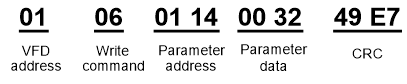
After receiving the command, the VFD converts 50 into 5.0 based on the fieldbus scale, and then sets "Wake-up-from-sleep delay" to 5.0s.
For another example, after the upper computer transmits the "Wake-up-from-sleep delay" parameter read command, the master receives the following response from the VFD:
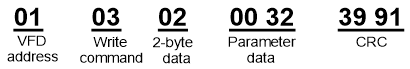
The parameter data is 0032H, that is, 50, so 5.0 is obtained based on the fieldbus scale (50/10=5.0). In this case, the master identifies that the "Wake-up-from-sleep delay" is 5.0s.
9.4.7 Error message response
Operation errors may occur in communication-based control. For example, some parameters can only be read, but a write command is transmitted. In this case, the VFD returns an error message response.
Error message responses are sent from the VFD to the master. The following table describes the codes and definitions of the error message responses.
Code | Name | Description |
01H | Invalid command | The command code received by the upper computer is not allowed to be executed. The possible causes are as follows: • The function code is applicable only on new devices and is not implemented on this device. • The slave is in the faulty state when processing this request. |
02H | Invalid data address | For the VFD, the data address in the request of the upper computer is not allowed. In particular, the combination of the register address and the number of the to-be-transmitted bytes is invalid. |
03H | Invalid data value | The received data domain contains a value that is not allowed. The value indicates the error of the remaining structure in the combined request. Note: It does not mean that the data item submitted for storage in the register includes a value unexpected by the program. |
04H | Operation failure | The parameter is set to an invalid value in the write operation. For example, a function input terminal cannot be set repeatedly. |
05H | Password error | The password entered in the password verification address is different from that set in P07.00. |
06H | Data frame error | The length of the data frame transmitted by the upper computer is incorrect, or in the RTU format, the value of the CRC check bit is inconsistent with the CRC value calculated by the lower computer. |
07H | Parameter read-only | The parameter to be modified in the write operation of the upper computer is a read-only parameter. |
08H | Parameter cannot be modified in running | The parameter to be modified in the write operation of the upper computer cannot be modified during the running of the VFD. |
09H | Password protection | A user password is set, and the upper computer does not provide the password to unlock the system when performing a read or write operation. The error of "system locked" is reported. |
When returning a response, the slave device uses a function code domain and fault address to indicate whether it is a normal response (no error) or exception response (some errors occur). In a normal response, the device returns the corresponding function code and data address or sub-function code. In an exception response, the device returns a code that is equal to a normal code, but the first bit is logic 1.
For example, if the master device transmits a request message to a slave device for reading a group of function code address data, the code is generated as follows:
0 0 0 0 0 0 1 1 (03H in the hexadecimal form)
For an exception response, the following code is returned:
1 0 0 0 0 0 1 1 (83H in the hexadecimal form)
In addition to the modification of the code, the slave device returns a byte of exception code that describes the cause of the exception. After receiving the exception response, the typical processing of the master device is to transmit the request message again or modify the command based on the fault information.
For example, to set the "Channel of running commands" (P00.01, the parameter address is 0001H) of the VFD whose address is 01H to 03, the command is as follows:
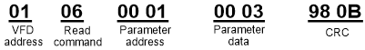
However, the setting range of the "Running command channel" is 0 to 2. The value 3 exceeds the setting range. In this case, the VFD returns an error message response as shown in the following:
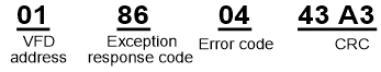
The exception response code 86H (generated based on the highest-order bit "1" of the write command 06H) indicates that it is an exception response to the write command (06H). The error code is 04H. From the preceding table, we can see that it indicates the error "Operation failure", which means "The parameter is set to an invalid value in the write operation".
9.4.8 Read/Write operation example
For details about the formats of the read and write commands, see sections 9.4.1 and 9.4.2.
9.4.8.1 Examples of read command 03H
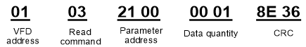
Example 1: Read status word 1 of the VFD whose address is 01H. According to the table of other function addresses, the parameter address of status word 1 of the VFD is 2100H.
The read command transmitted to the VFD is as follows:
Assume that the following response is returned:
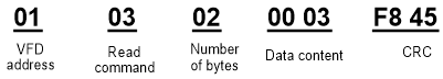
The data content returned by the VFD is 0003H, which indicates that the VFD is in the stopped state.
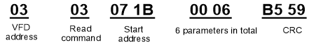
Example 2: View information about the VFD whose address is 03H, including "Present fault type" (P07.27) to "5th-last fault type" (P07.32) of which the parameter addresses are 071BH to 0720H (contiguous 6 parameter addresses starting from 071BH).
The command transmitted to the VFD is as follows:
Assume that the following response is returned:
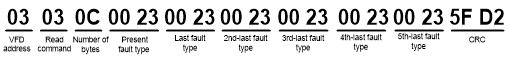
According to the returned data, all the fault types are 0023H, that is, 35 in the decimal form, which means the maladjustment fault (STo)
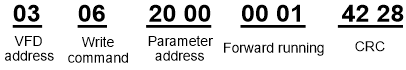
9.4.8.2 Examples of write command 06H
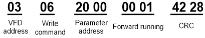
Example 1: Set the VFD whose address is 03H to be forward running. Refer to the table of other function parameters, the address of "Communication-based control command" is 2000H, and 0001H indicates forward running.
Function | Address | Data description | R/W |
Communication-based control command | 2000H | 0001H: Forward running | R/W |
0002H: Reverse running | |||
0003H: Forward jogging | |||
0004H: Reverse jogging | |||
0005H: Stop | |||
0006H: Coast to stop (emergency stop) | |||
0007H: Fault reset | |||
0008H: Jogging to stop |
The command transmitted by the master is as follows:
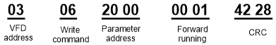
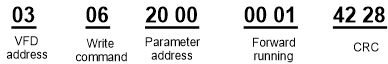
If the operation is successful, the following response is returned (same as the command transmitted by the master):
Example 2: Set the "Max. output frequency" of the VFD whose address is 03H to 100 Hz.
Function code | Name | Description | Setting range | Default | Modify |
P00.03 | Max. output frequency | P00.04–600.00H (400.00Hz) | 100.00–600.00 | 50.00Hz | ◎ |
According to the number of decimals, the fieldbus scale of the "Max. output frequency" (P00.03) is 100. Multiply 100 Hz by 100. The value 10000 is obtained, and it is 2710H in the hexadecimal form.
The command transmitted by the master is as follows:
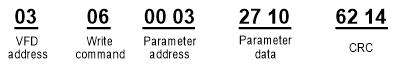
If the operation is successful, the following response is returned (same as the command transmitted by the master):
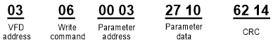
Note: In the preceding command description, spaces are added to a command just for explanatory purposes. In practical applications, no space is required in the commands.
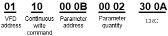
9.4.8.3 Examples of continuously write command 10H
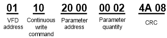
Example 1: Set the VFD whose address is 01H to be forward running at the frequency of 10 Hz. Refer to the table of other function parameters, the address of "Communication-based control command" is 2000H, 0001H indicates forward running, and the address of "Communication-based value setting" is 2001H, as shown in the following figure. 10 Hz is 03E8H in the hexadecimal form.
Function | Address | Data description | R/W |
Communication-based control command | 2000H | 0001H: Forward running | R/W |
0002H: Reverse running | |||
0003H: Forward jogging | |||
0004H: Reverse jogging | |||
0005H: Stop | |||
0006H: Coast to stop (emergency stop) | |||
0007H: Fault reset | |||
0008H: Jogging to stop | |||
Communication-based value setting | 2001H | Communication-based frequency setting (0–Fmax, unit: 0.01 Hz) | R/W |
2002H | PID setting, range (0–1000, 1000 corresponding to 100.0%) |
In the actual operation, set P00.01 to 2 and P00.06 to 8.
The command transmitted by the master is as follows:
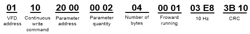
If the operation is successful, the following response is returned:
Example 2: Set "ACC time" of the VFD whose address is 01H to 10s, and "DEC time" to 20s.
ACC time 1 | Model depended | ○ | ||
DEC time 1 | Model depended | ○ |
The address of P00.11 is 000B, 10s is 0064H in the hexadecimal form, and 20s is 00C8H in the hexadecimal form.
The command transmitted by the master is as follows:
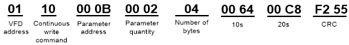
If the operation is successful, the following response is returned:
Note: In the preceding command description, spaces are added to a command just for explanatory purposes. In practical applications, no space is required in the commands.
9.4.8.4 Modbus communication commissioning example
A PC is used as the host, an RS232-RS485 converter is used for signal conversion, and the PC serial port used by the converter is COM1 (an RS232 port). The upper computer commissioning software is the serial port commissioning assistant Commix, which can be downloaded from the Internet. Download a version that can automatically execute the CRC check function. The following figure shows the interface of Commix.
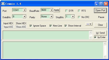
First, set the serial port to COM1. Then, set the baud rate consistently with P14.01. The data bits, check bits, and end bits must be set consistently with P14.02. If the RTU mode is selected, you need to select the hexadecimal form Input HEX. To set the software to automatically execute the CRC function, you need to select ModbusRTU, select CRC16 (MODBU SRTU), and set the start byte to 1. After the auto CRC check function is enabled, do not enter CRC information in commands. Otherwise, command errors may occur due to repeated CRC check.
The commissioning command to set the VFD whose address is 03H to be forward running is as follows:
Note:
Set the address (P14.00) of the VFD to 03.
Set "Channel of running commands" (P00.01) to "Communication", and set "Communication channel of running commands" (P00.02) to the Modbus communication channel.
Click Send. If the line configuration and settings are correct, a response transmitted by the VFD is received as follows: