C.4.1 Wall-mounting dimensions
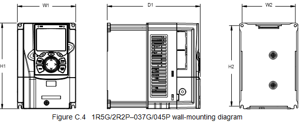
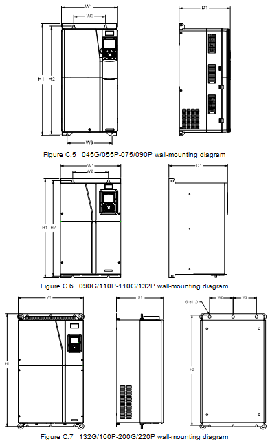
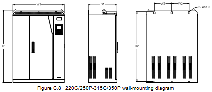
Table C.1 Wall-mounting dimensions (unit: mm)
VFD model | W1 | W2 | W3 | H1 | H2 | D1 | Installation hole diameter | Screw |
1R5G/2R2P–2R2G/003P | 126 | 115 | - | 186 | 175 | 185 | 5 | M4 |
004G/5R5P–5R5G/7R5P | 126 | 115 | - | 186 | 175 | 201 | 5 | M4 |
7R5G/011P | 146 | 131 | - | 256 | 243.5 | 192 | 6 | M5 |
011G/015P–015G/018P | 170 | 151 | - | 320 | 303.5 | 220 | 6 | M5 |
018G/022P–022G/030P | 200 | 185 | - | 340.6 | 328.6 | 208 | 6 | M5 |
030G/037P–037G/045P | 250 | 230 | - | 400 | 380 | 223 | 6 | M5 |
045G/055P–075/090P | 282 | 160 | 226 | 560 | 542 | 258 | 9 | M8 |
090/110P–110G/132P | 338 | 200 | - | 554 | 535 | 330 | 10 | M8 |
132G/160P–200G/220P | 500 | 180 | - | 870 | 850 | 360 | 11 | M10 |
220G/250P–315G/355P | 680 | 230 | - | 960 | 926 | 380 | 13 | M12 |
C.4.2 Flange installation dimensions
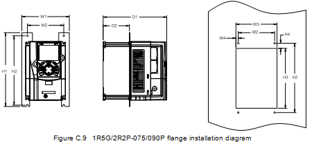
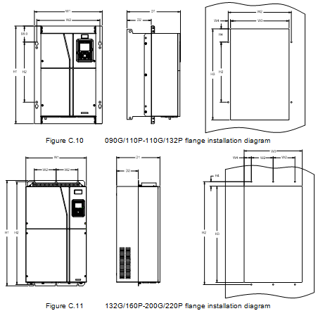
Table C.2 380V flange installation dimensions (unit: mm)
VFD model | W1 | W2 | W3 | W4 | H1 | H2 | H3 | H4 | D1 | D2 | Hole diameter | Screw |
1R5G/2R2P–2R2G/003P | 150.2 | 115 | 130 | 7.5 | 234 | 220 | 190 | 13.5 | 185 | 65.5 | 5 | M4 |
004G/5R5P–5R5G/7R5P | 150.2 | 115 | 130 | 7.5 | 234 | 220 | 190 | 13.5 | 201 | 83 | 5 | M4 |
7R5G/011P | 170.2 | 131 | 150 | 9.5 | 292 | 276 | 260 | 6 | 192 | 84.5 | 6 | M5 |
011G/015P–015G/018P | 191.2 | 151 | 174 | 11.5 | 370 | 351 | 324 | 12 | 220 | 113 | 6 | M5 |
018G/022P–022G/030P | 266 | 250 | 224 | 13 | 371 | 250 | 350.6 | 20.3 | 208 | 104 | 6 | M5 |
030G/037P–037G/045P | 316 | 300 | 274 | 13 | 430 | 300 | 410 | 55 | 223 | 118.3 | 6 | M5 |
045G/055P–075/090P | 352 | 332 | 306 | 12 | 580 | 400 | 570 | 80 | 258 | 133.8 | 9 | M8 |
090/110P–110G/132P | 418.5 | 389.5 | 361 | 14.2 | 600 | 370 | 559 | 108.5 | 330 | 149.5 | 10 | M8 |
132G/160P–200G/220P | 500 | 180 | 480 | 60 | 870 | 850 | 796 | 37 | 360 | 178.5 | 11 | M10 |
C.4.3 Floor installation dimensions
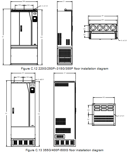
Table C.3 380V floor installation dimensions (unit: mm)
VFD model | W1 | W2 | W3 | W4 | H1 | H2 | D1 | D2 | Hole diameter | Screw |
220G/250P–315G/355P | 750 | 230 | 714 | 680 | 1410 | 1390 | 380 | 150 | 13/12 | M12/M10 |
355G/400P-500G | 620 | 230 | 572 | - | 1700 | 1678 | 560 | 240 | 22/12 | M20/M10 |