3.3.1 Main circuit connection diagram

Figure 3‑6 Main circuit connection diagram of 380V VFDs
Note:
The fuse, input reactor, input filter, output reactor, output filter are optional parts. Please refer to Appendix D and Appendix E for detailed information.
3.3.2 Main circuit terminals diagram

Figure 3‑7 Main circuit terminals diagram of VFDs of 380V (7.5–15kW)
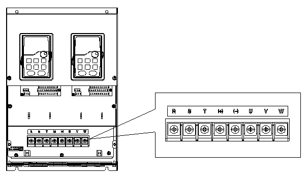
Figure 3‑8 Main circuit terminals diagram of VFDs of 380V (18.5–30kW)

Figure 3‑9 Main circuit terminals diagram of VFDs of 380V (37–55kW)
Terminal | Description |
R, S, T | Three-phase power input terminals |
(+) , (-) | Anode and cathode of the DC bus |
U, V, W | Three-phase AC output terminals |
PE, | Grounding terminals |
3.3.3 Main circuit terminal wiring
1. Connect the ground line of input power cable to the ground terminal of VFD (PE) directly, and connect 3PH input cable to R, S and T and fasten up.
2. Connect the ground line of motor cable to the ground terminal of the VFD, and connect the 3PH motor cable to U, V, W and fasten up.
3. Connect the brake resistor which carries cables to the designated position.
4. Fasten up all the cables on the outside of the VFD if allowed.

Figure 3‑10 Correct installation of the screw
3.3.4 Control circuit wiring and terminals
3.3.4.1 Control circuit wiring diagram of rectifier

Figure 3‑11 Control circuit wiring diagram of rectifier
3.3.4.2 Control circuit terminal of rectifier

Figure 3‑12 Rectifier control circuit terminal
Table 3‑1 Terminals in rectification control circuit
Type | Identifier | Name | Description | |
Input phase detection | R | Input phase R | Three-phase mains input terminals, detecting mains phases RS and ST Detection voltage range: AC 0–690V Note: Pay attention to the wiring sequence. | |
S | Input phase S | |||
T | Input phase T | |||
Output phase detection | U | Reserved | ||
V | ||||
W | ||||
Power | +10V | 10V reference power supply | 10V reference power supply Max. output current: 50mA As the adjusting power supply of the external potentiometer Potentiometer resistance: above 5 kΩ | |
+24V | 24V power supply | To provide 24V±10% power supply externally, with the max. output current of 200mA Generally serving as the power supply of digital input and output or the power supply of the external sensor | ||
COM | Common terminal of 10V | |||
GND | Common terminal of 24V | |||
Analog input and output | AI1 | Analog input 1 | 1. Input range: 0–10V or 0–20mA for AI1 2. Input impedance: 20kΩ for voltage input and 500Ω for current input 3. The input type (voltage or current) is set through the jumper. 4. Resolution: When 10V corresponds to 50Hz, the min. resolution is 5mV. 5. Deviation: ±1%, 25°C | |
AO1 | Analog output 1 | 1. Output range: 0–10V or 0–20mA 2. The output type (voltage or current) is set through the jumper. 3. Resolution: 12 bits; accuracy: 1% 4. Deviation: ±1%, 25°C | ||
Digital input and output | S1 | Digital input 1 | 1. Internal impedance: 3.3kΩ | |
S2 | Digital input 2 | |||
S3 | Digital input 3 | |||
S4 | Digital input 4 | |||
S5 | Digital input 5 | |||
S6 | AC buffer contactor actuation feedback signal input | |||
Communication | 485+ | RS485 communication | RS485 communication terminals, using the Modbus protocol | |
485- | ||||
Relay output | RO1A | Relay 1 NO contactor | 1. Contactor capacity: 3A/AC250V, 1A/DC30V | |
RO1B | Relay 1 NC contactor | |||
RO1C | Relay 1 common contactor | |||
RO2A | Relay 2 NO contactor | |||
RO2B | Relay 2 NC contactor | |||
RO2C | Relay 2 common contactor |
3.3.4.3 Converting control circuit wiring

Figure 3‑13 Converting control circuit wiring
3.3.4.4 Terminals in converting control circuit

Figure 3‑14 Terminals in converting control circuit
Table 3‑2 Terminals in converting control circuit
Type | Identifier | Name | Description |
Power | +10V | +10V reference power supply | GND as the reference Setpoint 10.5V Max. output current: 100mA With output short-circuit protection Accuracy: 1% |
+24V | 24V power supply | COM as the reference With output short-circuit protection Max. current provided externally: 100mA Accuracy: 10% Generally serving as the digital input and output working power supply or the power supply of the external sensor | |
PW | External power | COM as the reference, providing the working power for digital input and output from the external to the internal Input voltage range: DC12–30V | |
Analog input | AI1 | Analog input 1 | GND as the reference 1. Input range: 0–10V or 0–20mA 2. The input type (voltage or current) is set through the jumper J3. 3. Resolution: 12 bits 4. Deviation: ±1%, 25°C |
AI2 | Analog input 2 | GND as the reference 1. Input range: 0–10V or 0–20mA 2. The input type (voltage or current) is set through the jumper J4. 3. Resolution: 12 bits 4. Deviation: ±1%, 25°C | |
AI3 | Analog input 3 | GND as the reference 1. Input range: -10–10V 3. The voltage input is selected through the function code. 4. Resolution: 12 bits 5. Deviation:±1%, 25°C | |
Analog output | AO1 | Analog output 1 | GND as the reference 1. Output range: -10V–10V or -20mA–20mA 2. The input type (voltage or current) is set through the jumpers J1 and J2. 3. Deviation:±1%, 25°C |
AO2 | Analog output 2 | ||
Digital input and output | S1 | Digital input 1 | COM as the reference 1. Internal impedance: 3.3kΩ 2. Acceptable input voltage: 12–30V 3. Dual-directional input terminals, supporting NPN and PNP 4. Max input frequency: 1kHz 5: For HDI, max. input frequency: 50kHz |
S2 | Digital input 2 | ||
S3 | Digital input 3 | ||
S4 | Digital input 4 | ||
S5 | Digital input 5 | ||
S6 | Digital input 6 | ||
S7 | Digital input 7 | ||
S8 | Digital input 8 | ||
HDI | High speed pulse input | ||
Y1 | Open collector output | COM as the reference 1. Contact capacity: 200mA/30V 2. Output frequency range: 0–1kHz, OC output 3. Input power: DC12–30V | |
HDO | Open collector output or open collector high speed pulse output | COM as the reference 1. Output voltage amplitude: 24V 2. Output frequency: 50kHz | |
Relay output | RO1A | Relay 1 NO contactor | 1. Contactor capacity: AC250V/3A, DC30V/1A 2. Not able to function as high-frequency digital output |
RO1B | Relay 1 NC contactor | ||
RO1C | Relay 1 common contactor | ||
RO2A | Relay 2 NO contactor | ||
RO2B | Relay 2 NC contactor | ||
RO2C | Relay 2 common contactor | ||
Communication | 485+ 485- | RS485 communication | RS485 communication terminals, using the Modbus protocol |
Others | PE | Shield ground | Used for grounding the shield layer in terminal wiring, such as the shield layers of the analog signal cable, RS485 communication cable, and motor cable |
COM | Common terminal | Common terminal of +24V | |
CME | Common terminal | Common terminal of open collector output |
3.3.5 Input /Output signal connection figure
Use U-shaped short-circuit connectors to set NPN mode or PNP mode and the internal or external power supply. The default setting is NPN internal mode.

Figure 3‑15 U-shaped short-circuit positions
If the signal is from NPN transistor, set the U-shaped short-circuit connector between +24V and PW as follows according to the used power supply.

Figure 3‑16 NPN modes
If the signal is from PNP transistor, set the U-shaped short-circuit connector as follows according to the used power supply.

Figure 3‑17 PNP modes