B.3.1 Command code: 03H, read N words (Max. continuous reading is 16 words)
Command code 03H means that if the master read data for the VFD, the reading number depends on the "data number" in the command code. The Max. continuous reading number is 16 and the parameter address should be continuous. The byte length of every data is 2 (one word). The following command format is illustrated by hex (a number with "H" means hex) and one hex occupies one byte.
The command code is used to read the working stage of the VFD.
For example, read continuous 2 data content from 0004H from the VFD with the address of 01H (read the content of data address of 0004H and 0005H), the frame structure is as below:
RTU master command message (from the master to the VFD)
START | T1-T2-T3-T4 (transmission time of 3.5 bytes) |
ADDR | 01H |
CMD | 03H |
High bit of the start bit | 00H |
Low bit of the start bit | 04H |
High bit of data number | 00H |
Low bit of data number | 02H |
CRC low bit | 85H |
CRC high bit | CAH |
END | T1-T2-T3-T4(transmission time of 3.5 bytes) |
"Start address" means reading data from the address and it occupies 2 bytes with the fact that the high bit is in the front and the low bit is in the behind.
"Data number" means the reading data number with the unit of word. If the "start address" is 0004H and the "data number" is 0002H, the data of 0004H and 0005H will be read.
CRC occupies 2 bytes with the fact that the low bit is in the front and the high bit is in the behind.
RTU slave response message (from the VFD to the master)
START | T1-T2-T3-T4 (transmission time of 3.5 bytes) |
ADDR | 01H |
CMD | 03H |
Byte number | 04H |
Data high bit of address 0004H | 13H |
Data low bit of address 0004H | 88H |
Data high bit of address 0005H | 00H |
Data low bit of address 0005H | 00H |
CRC low bit | 7EH |
CRC high bit | 9DH |
END | T1-T2-T3-T4 (transmission time of 3.5 bytes) |
The meaning of the response is that:
ADDR=01H means the command message is sent to the VFD with the address of 01H and ADDR occupies one byte;
CMD=03H means the message is received from the VFD to the master for the response of reading command and CMD occupies one byte;
"Byte number" means all byte number from the byte (excluding the byte) to CRC byte (excluding the byte). 04 means there are 4 byte of data from the "byte number" to "CRC low bit", which are "digital address 0004H high bit", "data low bit of address 0004H", "data high bit of address 0005H" and "data low bit of address 0005H".
There are 2 bytes stored in one data with the fact that the high bit is in the front and the low bit is in the behind of the message, the data of address 0004H is 1388H, and the data of address 0005H is 0000H.
CRC occupies 2 bytes with the fact that the low bit is in the front and the high bit is in the behind.
B.3.2 Command code: 06H, write one word
The command means that the master write data to the VFD and one command can write one data other than multiple data. The effect is to change the working mode of the VFD.
For example, write 5000 (1388H) to 0004H from the VFD with the address of 02H, the frame structure is as below:
RTU master command message (from the master to the VFD)
START | T1-T2-T3-T4 (transmission time of 3.5 bytes) |
ADDR | 02H |
CMD | 06H |
High bit of writing data address | 00H |
Low bit of writing data address | 04H |
High bit of data content | 13H |
Low bit of data content | 88H |
CRC low bit | C5H |
CRC high bit | 6EH |
END | T1-T2-T3-T4 (transmission time of 3.5 bytes) |
RTU slave response message (from the VFD to the master)
START | T1-T2-T3-T4 (transmission time of 3.5 bytes) |
ADDR | 02H |
CMD | 06H |
High bit of writing data address | 00H |
Low bit of writing data address | 04H |
High bit of data content | 13H |
Low bit of data content | 88H |
CRC low bit | C5H |
CRC high bit | 6EH |
END | T1-T2-T3-T4 (transmission time of 3.5 bytes) |
B.3.3 Command code: 08H, diagnosis function
Meaning of sub-function codes:
Sub-function code | Description |
0000 | Return to inquire information data |
For example: The inquiry information string is same as the response information string when the loop detection to address 01H of driver is carried out.
RTU request command:
START | T1-T2-T3-T4 (transmission time of 3.5 bytes) |
ADDR | 01H |
CMD | 08H |
High bit of sub-function code | 00H |
Low bit of sub-function code | 00H |
High bit of data content | 12H |
Low bit of data content | ABH |
CRC CHK low bit | ADH |
CRC CHK high bit | 14H |
END | T1-T2-T3-T4 (transmission time of 3.5 bytes) |
RTU response command:
START | T1-T2-T3-T4 (transmission time of 3.5 bytes) |
ADDR | 01H |
CMD | 08H |
High bit of sub-function code | 00H |
Low bit of sub-function code | 00H |
High bit of data content | 12H |
Low bit of data content | ABH |
CRC CHK low bit | ADH |
CRC CHK high bit | 14H |
END | T1-T2-T3-T4 (transmission time of 3.5 bytes) |
B.3.4 Command code: 10H, continuous writing
Command code 10H means that if the master writes data to the VFD, the data number depends on the "data number" in the command code. The max. continuous reading number is 16.
For example, write 5000(1388H) to 0004H of the VFD whose slave address is 02H and 50(0032H) to 0005H, the frame structure is as below:
RTU request command:
START | T1-T2-T3-T4 (transmission time of 3.5 bytes) |
ADDR | 02H |
CMD | 10H |
High bit of writing data address | 00H |
Low bit of writing data address | 04H |
High bit of data number | 00H |
Low bit of data number | 02H |
Byte number | 04H |
High bit of data 0004H | 13H |
Low bit of data 0004H | 88H |
High bit of data 0005H | 00H |
Low bit of data 0005H | 32H |
CRC low bit | C5H |
CRC high bit | 6EH |
END | T1-T2-T3-T4 (transmission time of 3.5 bytes) |
RTU response command:
START | T1-T2-T3-T4 (transmission time of 3.5 bytes) |
ADDR | 02H |
CMD | 10H |
High bit of writing data address | 00H |
Low bit of writing data address | 04H |
High bit of data number | 00H |
Low bit of data number | 02H |
CRC low bit | C5H |
CRC high bit | 6EH |
END | T1-T2-T3-T4 (transmission time of 3.5 bytes) |
B.3.5 Data address definition
The address definition of the communication data in this part is to control the running of the VFD and get the state information and relative function parameters of the VFD.
B.3.5.1 Rules of parameter address of the function codes
The parameter address occupies 2 bytes with the fact that the high bit is in the front and the low bit is in the behind. The range of high and low byte is: high byte-00–ffH; low byte-00–ffH. The high byte is the group number before the radix point of the function code and the low byte is the number after the radix point. But both the high byte and the low byte should be changed into hex. For example P05.06, the group number before the radix point of the function code is 05, then the high bit of the parameter is 05, the number after the radix point 06, then the low bit of the parameter is 06, then t he function code address is 0506H and the parameter address of P10.01 is 0B.3H.
Function code | Name | Description | Setting range | Default |
P10.01 | Simple PLC memory | 0: Power loss without memory 1: Power loss with memory | 0–1 | 0 |
Note: P29 group is the factory parameter which cannot be read or changed. Some parameters cannot be changed when the VFD is in the running state and some parameters cannot be changed in any state. The setting range, unit and relative instructions should be paid attention to when modifying the function code parameters.
Besides, EEPROM is stocked frequently, which may shorten the usage time of EEPROM. For users, some functions are not necessary to be stocked on the communication mode. The needs can be met on by changing the value in RAM. Changing the high bit of the function code from 0 to 1 can also realize the function. For example, the function code P00.07 is not stocked into EEPROM. Only by changing the value in RAM can set the address to 8007H. This address can only be used in writing RAM other than reading. If it is used to read, it is an invalid address.
B.3.5.2 Description of other Modbus function addresses
The master can operate the parameters of the VFD as well as control the VFD, such as running or stopping and monitoring the working state of the VFD.
The following table lists other functions.
Function | Address definition | Data meaning | R/W | |
Communication control command | 2000H | 0001H:forward running | W/R | |
0002H:reverse running | ||||
0003H:forward jogging | ||||
0004H:reverse jogging | ||||
0005H:stop | ||||
0006H:coast to stop | ||||
0007H:fault reset | ||||
0008H:jogging stop | ||||
The address of the communication setting value | 2001H | Communication setting frequency(0–Fmax,unit: 0.01Hz)) | W/R | |
2002H | PID reference, range(0–1000, 1000 corresponds to100.0% ) | |||
2003H | PID feedback, range(0–1000, 1000 corresponds to100.0% ) | W/R | ||
2004H | Torque setting value (-3000–3000, 1000 corresponds to the 100.0% of the rated current of the motor) | W/R | ||
2005H | The upper limit frequency setting during forward rotation(0–Fmax(unit: 0.01Hz)) | W/R | ||
2006H | The upper limit frequency setting during reverse rotation(0–Fmax(unit: 0.01Hz)) | W/R | ||
2007H | The upper limit torque of electromotion torque (0–3000, 1000 corresponds to the 100.0% of the rated current of the motor) | W/R | ||
2008H | The upper limit torque of braking torque (0–3000, 1000 corresponds to the 100.0% of the rated current of the motor) | W/R | ||
2009H | Special control command word: Bit0–1: =00: motor 1 =01: motor 2 =10: motor 3 =11: motor 4 Bit2: =1 torque control =0: speed control Bit3: =1 power consumption cleared =0: power consumption retained Bit4: =1 pre-exciting =0: pre-exciting disabled Bit5: =1 DC braking =0: DC braking disabled | W/R | ||
200AH | Virtual input terminal command, range: 0x000–0x1FF | W/R | ||
200BH | Virtual output terminal command, range:0x00–0x0F | W/R | ||
200CH | Voltage set value (special for V/F separation) (0–1000, 1000 corresponds to the 100.0% of the rated voltage of the motor) | W/R | ||
200DH | AO output setting 1(-1000–1000, 1000 corresponds to 100.0%) | W/R | ||
200EH | AO output setting 2(-1000–1000, 1000 corresponds to 100.0%) | W/R | ||
SW 1 of the VFD | 2100H | 0001H:forward running | R | |
0002H:forward running | ||||
0003H:stop | ||||
0004H:fault | ||||
0005H: POFF state | ||||
0006H: VFD pre-exciting | ||||
SW 2 of the VFD | 2101H | Bit0: =0: not ready for running =1: ready for running Bi1–2:=00:motor 1 =01:motor 2 =10:motor 3 =11:motor 4 Bit3: =0:asynchronous motor =1:synchronous motor Bit4:=0:pre-alarm without overload =1:overload pre-alarm Bit5– Bit6:=00:keypad control =01:terminal control =10:commuincation control | R | |
Fault code of the VFD | 2102H | See the fault type instruction | R | |
Identifying code of the VFD | 2103H | GD300-----0x010a | R | |
Running frequency | 3000H | 0–Fmax(Unit: 0.01Hz) | VFD power consumption =MSB of power consumption *1000+ LSB of power consumption | R |
Output power | 3001H | -300.0–300.0%(Unit: 0.1%) | R | |
Output current | 3002H | 0.0–3000.0A(Unit: 0.1A) | R | |
VFD fault code | 3003H | See the fault type instruction. | R | |
Cooling fin temperature | 3004H | 0.0–300.0°(Unit: 0.1°) | R | |
Bus voltage | 3005H | 0.0–2000.0V(Unit: 0.1V) | R | |
Output torque | 3006H | -250.0–250.0%(Unit: 0.1%) | R | |
MSB of power consumption | 3007H | 0–65535kWh(*1000) | R | |
LSB of power consumption | 3008H | 0–999.9kWh(Unit: 0.1) | R | |
Set frequency | 3009H | 0–Fmax(Unit: 0.01Hz) | R | |
Input IO state | 300AH | 000–1FF | R | |
Output IO state | 300BH | 000–1FF | R | |
AI 1 | 300CH | 0.00–10.00V(Unit: 0.01V) | R | |
AI 2 | 300DH | 0.00–10.00V(Unit: 0.01V) | R | |
AI 3 | 300EH | -10.00–10.00V(Unit: 0.01V) | R | |
AI 4 | 300FH | R | ||
Read high speed pulse 1 input | 3010H | 0.00–50.00kHz(Unit: 0.01Hz) | R | |
Read high speed pulse 2 input | 3011H | R | ||
Read current step of the multi-step speed | 3012H | 0–15 | R | |
External length | 3013H | 0–65535 | R | |
External counting value | 3014H | 0–65535 | R | |
Torque setting | 3015H | -300.0–300.0%(Unit: 0.1%) | R | |
VFD code | 3016H | R | ||
Fault code | 5000H | R | ||
R/W characteristics means the function is with read and write characteristics. For example, "communication control command" is writing chrematistics and control the VFD with writing command (06H). R characteristic can only read other than write and W characteristic can only write other than read.
Note: when operate on the VFD with the table above, it is necessary to enable some parameters. For example, the operation of running and stopping, it is necessary to set P00.01 to communication running command channel and set P00.02 to Modbus communication channel. And when operate on "PID reference", it is necessary to set P09.00 to "Modbus communication setting".
The encoding rules for device codes (corresponds to identifying code 2103H of the VFD)
8 MSBs in Code | Meaning | 8 LSBs in Code | Meaning |
01 | GD | 0x08 | GD35 vector VFDs |
0x09 | GD35-H1 vector VFDs | ||
0x0a | GD300 vector VFDs | ||
0x0b | GD100 simple vector VFDs | ||
0x0c | GD200 general VFDs | ||
0x0d | GD10 mini VFDs |
B.3.6 Fieldbus scale
The communication data is expressed by hex in actual application and there is no radix point in hex. For example, 50.12Hz cannot be expressed by hex so 50.12 can be magnified by 100 times into 5012, so hex 1394H can be used to express 50.12.
A non-integer can be timed by a multiple to get an integer and the integer can be called fieldbus ratio values.
The fieldbus ratio values are referred to the radix point of the setting range or default value in the function parameter list. If there are figures behind the radix point (n=1), then the fieldbus ratio value m is 10n. Take the table as the example:
Function code | Name | Description | Setting range | Default |
P01.20 | Hibernation restore delay time | 0.0–3600.0s (valid when P01.19=2) | 0.0–3600.0 | 0.0s |
If there is one figure behind the radix point in the setting range or the default value, then the fieldbus ratio value is 10. If the data received by the upper monitor is 50, then the "hibernation restore delay time" is 5.0 (5.0=50/10).
If Modbus communication is used to control the hibernation restore delay time as 5.0s. Firstly, 5.0 can be magnified by 10 times to integer 50 (32H) and then this data can be sent.
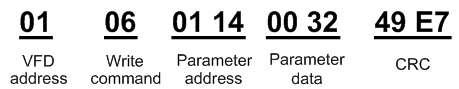
After the VFD receives the command, it will change 50 into 5 according to the fieldbus ratio value and then set the hibernation restore delay time as 5s.
Another example, after the upper monitor sends the command of reading the parameter of hibernation restore delay time ,if the response message of the VFD is as following:
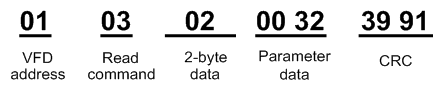
Because the parameter data is 0032H (50) and 50 divided by 10 is 5, then the hibernation restore delay time is 5s.
B.3.7 Fault message response
There may be fault in the communication control. For example, some parameter can only be read. If a writing message is sent, the VFD will return a fault response message.
The fault message is from the VFD to the master, its code and meaning is as below:
Code | Name | Meaning |
01H | Illegal command | The command from master can not be executed. The reason maybe: 1. This command is only for new version and this version can not realize. 2. Slave is in fault state and can not execute it. |
02H | Illegal data address | Some of the operation addresses are invalid or not allowed to access. Especially the combination of the register and the transmitting bytes are invalid. |
03H | Illegal value | When there are invalid data in the message framed received by slave. Note: This error code does not indicate the data value to write exceed the range, but indicate the message frame is an illegal frame. |
04H | Operation failed | The parameter setting in parameter writing is invalid. For example, the function input terminal can not be set repeatedly. |
05H | Password error | The password written to the password check address is not same as the password set by P7.00. |
06H | Data frame error | In the frame message sent by the upper monitor, the length of the digital frame is incorrect or the counting of CRC check bit in RTU is different from the lower monitor. |
07H | Written not allowed | It only happen in write command, the reason maybe: 1. The written data exceeds the parameter range. 2. The parameter should not be modified now. 3. The terminal has already been used. |
08H | The parameter cannot be changed during running | The modified parameter in the writing of the upper monitor can not be modified during running. |
09H | Password protection | When the upper monitor is writing or reading and the user password is set without password unlocking, it will report that the system is locked. |
The slave uses functional code fields and fault addresses to indicate it is a normal response or some error occurs (named as objection response). For normal responses, the slave shows corresponding function codes, digital address or sub-function codes as the response. For objection responses, the slave returns a code which equals the normal code, but the first byte is logic 1.
For example: when the master sends a message to the slave, requiring it to read a group of address data of the VFD function codes, there will be following function codes:
0 0 0 0 0 0 1 1 (Hex 03H)
For normal responses, the slave responds the same codes, while for objection responses, it will return:
1 0 0 0 0 0 1 1 (Hex 83H)
Besides the function codes modification for the objection fault, the slave will respond a byte of abnormal code which defines the error reason.
When the master receives the response for the objection, in a typical processing, it will send the message again or modify the corresponding order.
For example, set the "running command channel" of the VFD (P00.01, parameter address is 0001H) with the address of 01H to 03, the command is as following:
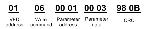
But the setting range of "running command channel" is 0–2, if it is set to 3, because the number is beyond the range, the VFD will return fault response message as below:
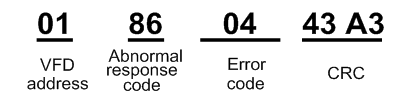
Abnormal response code 86H means the abnormal response to writing command 06H; the fault code is 04H. In the table above, its name is operation failed and its meaning is that the parameter setting in parameter writing is invalid. For example, the function input terminal can not be set repeatedly.
B.3.8 Example of writing and reading
See B.3.1 and B.3.2 for the command formats.
B.3.8.1 Example of reading command 03H
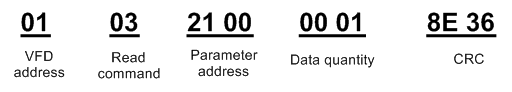
Example 1: Read the state word 1 of the VFD with the address of 01H (You can refer to the table of other Modbus function addresses). According to the table of other Modbus function addresses, the parameter address, the parameter address of the state word 1 of the VFD is 2100H.
The command sent to the VFD:
If the response message is as below:
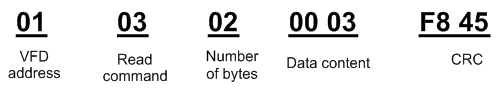
The data content is 0003H. According to the table, the VFD stops.
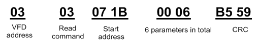
Example 2: Watch "the current fault type" to "the previous 5 times fault type" of the VFD through commands, the corresponding function code is P07.27–P07.32 and corresponding parameter address is 071BH–0720H (there are 6 from 071BH).
The command sent to the VFD:
If the response message is as below:

See from the returned data, all fault types are 0023H (decimal 35) with the meaning of maladjustment (STo).
B.3.8.2 Example of writing command 06H
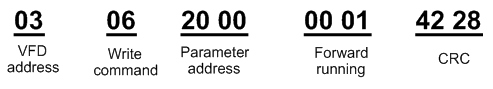
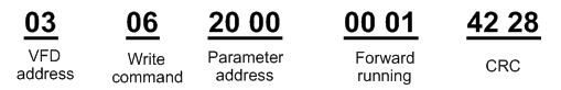
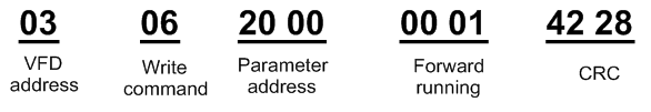
Example 1: Make the VFD with the address of 03H to run forward. According to the table of other Modbus function addresses, the address of "communication control command" is 2000H and forward running is 0001. See the table below.
Function | Address definition | Data meaning | R/W |
Communication control command | 2000H | 0001H:forward running | R/W |
0002H:reverse running | |||
0003H:forward jogging | |||
0004H:reverse jogging | |||
0005H:stop | |||
0006H:coast to stop | |||
0007H:fault reset | |||
0008H:jogging stop |
The command sent by the master:
If the operation is successful, the response may be as below (the same with the command sent by the master):
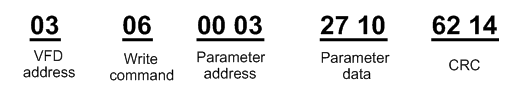
Example 2: Set the Max. output frequency of the VFD with the address of 03H as 100Hz.
Function code | Name | Description | Setting range | Default |
P00.03 | Max. output frequency | P00.04–400.00Hz | P00.04–400.00 | 50.00Hz |
See the figures behind the radix point, the fieldbus ratio value of the Max. output frequency (P00.03) is 100. 100Hz timed by 100 is 10000 and the corresponding hex is 2710H.
The command sent by the master:
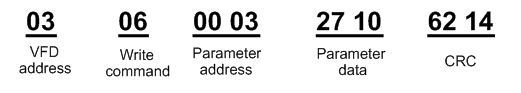
If the operation is success, the response may be as below (the same with the command sent by the master):
Note: The blank in the above command is for illustration and it cannot be added in the actual application.
B.3.8.3 Example of continous writing command 10H
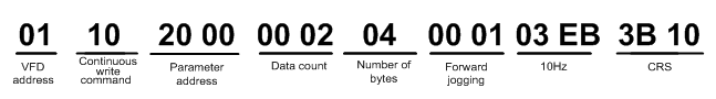
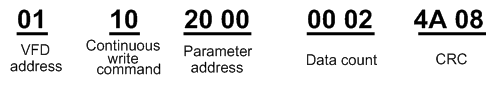
Example 1: make the VFD whose address is 01H run forward at 10Hz. Refer to the instruction of 2000H and 0001. Set the address of "communication setting frequency" is 2001H and 10Hz corresponds to 03E8H. See the table below.
Function | Address definition | Data meaning | R/W |
Communication control command | 2000H | 0001H:forward running | W/R |
0002H:reverse running | |||
0003H:forward jogging | |||
0004H:reverse jogging | |||
0005H:stop | |||
0006H:coast to stop (emergency stop) | |||
0007H:fault reset | |||
0008H:jogging stop | |||
The address of communication setting | 2001H | Communication setting frequency(0–Fmax(unit: 0.01Hz)) | W/R |
2002H | PID given, range(0–1000, 1000 corresponds to100.0% ) |
Set P00.01 to 2 and P00.06 to 8.
The command sent to the VFD:
If the response message is as below:
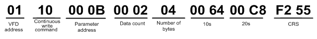
Example 2: set the ACC time of 01H VFD as 10s and the DEC time as 20s
Function code | Name | Description | Setting range | Default |
P00.11 | ACC time 1 | 0.0–3600.0s | 0.0–3600.0 | 20 |
P00.12 | DEC time 1 | 0.0–3600.0s | 0.0–3600.0 | 40 |
The corresponding address of P00.11 is 000B, the ACC time of 10s corresponds to 0064H, and the DEC time of 20s corresponds to 00C8H.
RTU mode:
The command sent to the VFD:
If the response message is as below:
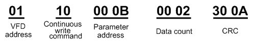
Note: the blank in the above command is for illustration. The blank can not be added in the actual application unless the upper monitor can remove the blank by them.
B.3.8.4 Example of Modbus communication commissioning
Assume that the master is a PC which uses RS232-RS485 converter to convert signals. The converter uses the PC serial port COM1 (RS232 port). The upper monitor commissioning software is the serial port commissioning assistant Commix 1.4, which is available in the Internet. It is recommended to use the software with the CRC function. The figure below shows an interface example of the software.
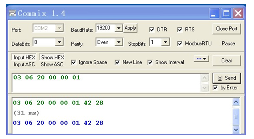
Set "Port" to "COM2". Set "BaudRate" to the value the same as that of P14.01. Keep "DataBits", "Parity", and "StopBits" consistent with the setting of P14.02. In RTU mode, select "HEX". If CRC must be enabled, select "ModbusRTU" and "CRC16(MODBUSRTU)", and set the starting byte to "1". Once after CRC is automatically enabled, you must not enter CRC in commands. Otherwise, repeated setting will cause command errors.
The commissioning command below enables the VFD with the address set to 03H to rotate forward (example 1 in section B.3.8.2):
Note:
1. Set the address (P14.00) of the VFD to 03.
2. Set "Channel of running commands" (P00.01) to "Communication", and set "Communication channel of running commands" (P00.02) to the Modbus communication channel.
3. Click Send. If the line configuration and settings are correct, a response transmitted by the VFD will be received.