|
 |
| Do not refit the VFD unless authorized; otherwise, fire, electric shock or other injuries may occur. |
| The base of the radiator may become hot during running. Do not touch to avoid hurt. |
| The electrical parts and components inside the VFD are electrostatic. Take measures to prevent electrostatic discharge during related operation. |


1.4.1 Delivery and installation
|
|

Note:
Select appropriate tools for delivery and installation to ensure a safe and proper running of the VFD and avoid physical injury or death. To ensure physical safety, the installation staff should take mechanical protective measures like wearing exposure shoes and working uniforms;
Ensure to avoid physical shock or vibration during delivery and installation;
Do not carry the VFD by its front cover only as the cover may fall off;
Installation site should be away from children and other public places;
The VFD should be used in proper environment (see section 4.2.1 "Installation environment" for details);
Prevent the screws, cables and other conductive parts from falling into the VFD;
As leakage current of the VFD during running may exceed 3.5mA, ground properly and ensure the grounding resistance is less than 10Ω. The conductivity of PE grounding conductor is the same with that of the phase conductor. For models higher than 30 kW, the cross sectional area of the PE grounding conductor can be slightly less than the recommended area.
R, S and T are the power input terminals, and U, V and W are output motor terminals. Connect the input power cables and motor cables properly; otherwise, damage to the VFD may occur.
1.4.2 Commissioning and running
|
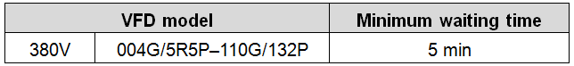
1. Disconnect all the input power sources including main power and control power. 2. Ensure the permanent-magnet synchronous motor has been stopped, and the voltage on output end of the VFD is lower than 36V. 3. After the permanent-magnet synchronous motor is stopped, wait for at least the time designated on the VFD, and ensure the voltage between "+" and "-" is lower than 36V. 4. During operation, it is a must to ensure the permanent-magnet synchronous motor cannot run again by the action of external load; it is recommended to install effective external brake device or disconnect the direct electrical connection between permanent-magnet synchronous motor and the VFD. |

Note:
Do not switch on or switch off input power sources of the VFD frequently;
For VFDs that have been stored for a long time, set the capacitance and carry out inspection and pilot run on the VFD before use.
Close the front cover before running; otherwise, electric shock may occur.
1.4.3 Maintenance and component replacement
|
|

Note:
Use proper torque to tighten the screws.
Keep the VFD and its parts and components away from combustible materials during maintenance and component replacement.
Do not carry out insulation voltage-endurance test on the VFD, or measure the control circuits of the VFD with megameter.
Take proper anti-static measures on the VFD and its internal parts during maintenance and component replacement.
1.4.4 Scrap treatment
| The heavy metals inside the VFD should be treated as industrial effluent. |
| When the life cycle ends, the product should enter the recycling system. Dispose of it separately at an appropriate collection point instead of placing it in the normal waste stream. |

