The Goodrive350 IP54 high-ingress protection series VFD is used to control asynchronous AC induction motor and permanent-magnet synchronous motor. The figure below shows the main circuit diagram of the VFD. The rectifier converts 3PH AC voltage into DC voltage, and the capacitor bank of intermediate circuit stabilizes the DC voltage. The inverter converts DC voltage into the AC voltage used by AC motor. When the circuit voltage exceeds the max-imum. limit value, external brake resistor will be connected to intermediate DC circuit to consume the feedback energy.
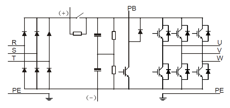
Figure 3–1 (015G/018P and below) main circuit diagram
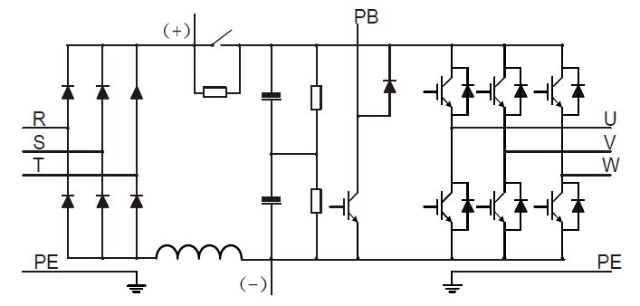
Figure 3–2 018G/022P–110G/132P (inclusive) main circuit diagram
Note:
1. VFDs of 018G/022P–110G/132P (inclusive) are equipped with built-in DC reactors.
2. Built-in brake units are included in the standard configuration of 037G/045P or lower models. The models that carry built-in brake units can also be connected to external brake resistors. The brake resistors are optional parts.
3. VFDs of 045G/055P–110G/132P models support optional built-in brake units. A VFD model with built-in brake unit ends with "-B", for example, GD350-045G-45-B.