C.3.1 Wall-mounting dimensions
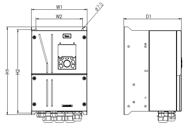
Figure C–2 Wall-mounting diagram of VFDs of 004G/5R5P–022G/030P
Table C‑1 Wall-mounting dimensions of VFDs (unit: mm)
VFD model | W1 | W2 | H1 | H2 | D1 | Installation hole diameter | Fixing screw | Net weight (kg) | Gross weight (kg) |
004G/5R5P–5R5G/7R5P | 196 | 164 | 296 | 282 | 212 | 6 | M5 | 7 | 8.5 |
7R5G/011P–015G/018P | 223 | 187 | 352 | 335.5 | 231 | 7 | M6 | 10.6 | 12.5 |
018G/022P–022G/030P | 274 | 234 | 399 | 380.5 | 231 | 7 | M6 | 17.7 | 20.1 |
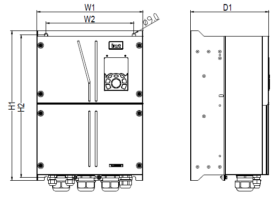
Figure C–3 Wall-mounting diagram of VFDs of 030G/037P-037G/045P
Table C‑2 Wall-mounting dimensions of VFDs (unit: mm)
VFD model | W1 | W2 | H1 | H2 | D1 | Installation hole diameter | Fixing screw | Net weight (kg) | Gross weight (kg) |
030G/037P–037G/045P | 318 | 263 | 447 | 426.5 | 235 | 9 | M8 | 23.4 | 26.1 |
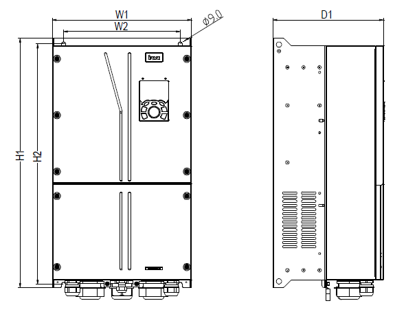
Figure C–4 Wall-mounting diagram of VFDs of 045G/055P-055G/075P
Table C‑3 Wall-mounting dimensions of VFDs (unit: mm)
VFD model | W1 | W2 | H1 | H2 | D1 | Installation hole diameter | Fixing screw | Net weight (kg) | Gross weight (kg) |
045G/055P | 338 | 283 | 610 | 588.5 | 269 | 9 | M8 | 38 | 42 |
055G/075P | 338 | 283 | 610 | 588.5 | 269 | 9 | M8 | 41 | 44.8 |
C.3.2 Flange installation dimensions
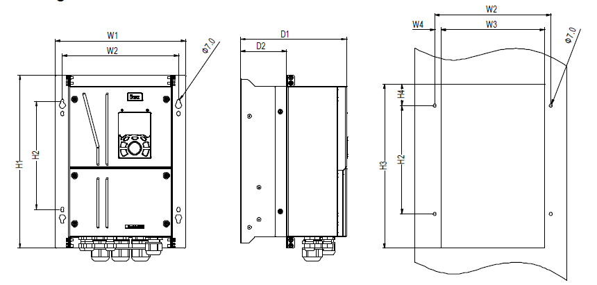
Figure C–5 Flange installation diagram of VFDs of 004G/5R5P-022G/030P
Table C‑4 Flange installation dimensions of VFDs (unit: mm)
VFD model | W1 | W2 | W3 | W4 | H1 | H2 | H3 | H4 | D1 | D2 | Installation hole diameter | Fixing screw | Net weight (kg) | Gross weight (kg) |
004G/5R5P–5R5G/7R5P | 256 | 232 | 212.6 | 9.7 | 328 | 213.5 | 298 | 29 | 212 | 78.5 | 6 | M5 | 7 | 8.5 |
7R5G/011P–015G/018P | 283 | 253 | 233.6 | 9.7 | 374 | 233.5 | 354 | 47 | 231 | 100.5 | 7 | M6 | 10.6 | 12.5 |
018G/022P–022G/030P | 334 | 310 | 290.6 | 9.7 | 433 | 273.5 | 401 | 50.5 | 231 | 100.5 | 7 | M6 | 17.7 | 20.1 |
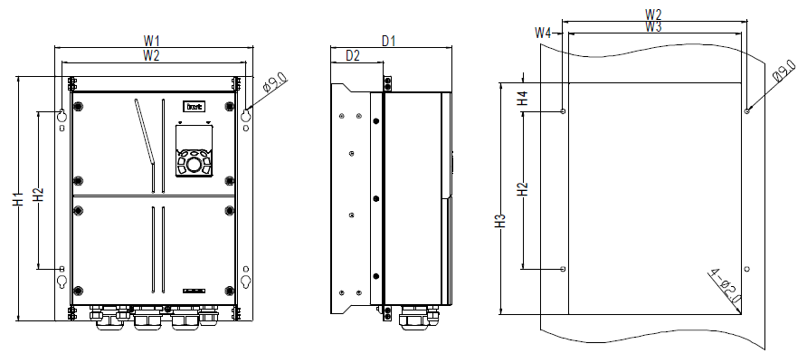
Figure C–6 Flange installation diagram of VFDs of 030G/037P–037G/045P
Table C‑5 Flange installation dimensions of VFDs (unit: mm)
VFD model | W1 | W2 | W3 | W4 | H1 | H2 | H3 | H4 | D1 | D2 | Installation hole diameter | Fixing screw | Net weight (kg) | Gross weight (kg) |
030G/037P–037G/045P | 386 | 358 | 335.6 | 11.2 | 477 | 307 | 449 | 54.5 | 212 | 78.5 | 9 | M8 | 23.4 | 26.1 |
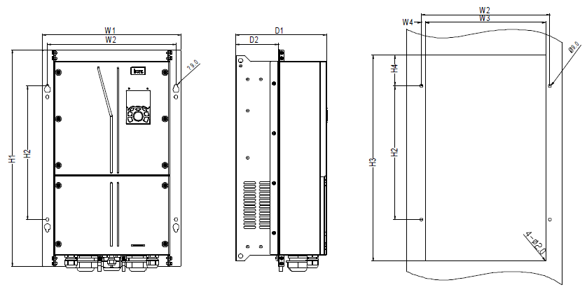
Figure C–7 Flange installation diagram of VFDs of 037G/045P–055G/075P
Table C‑6 Flange installation dimensions of VFDs (unit: mm)
VFD model | W1 | W2 | W3 | W4 | H1 | H2 | H3 | H4 | D1 | D2 | Installation hole diameter | Fixing screw | Net weight (kg) | Gross weight (kg) |
045G/055P | 410 | 380 | 335.6 | 12.2 | 644 | 397 | 612 | 91 | 269 | 126.5 | 9 | M8 | 38 | 42 |
055G/075P | 410 | 380 | 335.6 | 12.2 | 644 | 397 | 612 | 91 | 269 | 126.5 | 9 | M8 | 41 | 44.8 |