D.8.1 Brake component selection
When a VFD driving a high-inertia load decelerates or needs to decelerate abruptly, the motor runs in the power generation state and transmits the load-carrying energy to the DC circuit of the VFD, causing the bus voltage of the VFD to rise. If the bus voltage exceeds a specific value, the VFD reports an overvoltage fault. To prevent this from happening, you need to configure brake components.
|
|
| Connect the brake components to the VFD according to the wiring diagram. If the wiring is not properly performed, damage to the VFD or other devices may be caused. |


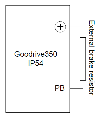
Goodrive350 IP54 high-ingress protection series VFDs of 037G/045P or lower are equipped with built-in brake units, Select brake resistors according to the specific requirements (such as the brake torque and brake usage requirements) on site.
Table D‑6 Brake unit signals
VFD model | Brake unit model | Resistance applicable for 100% brake torque (Ω) | Dissipated power of brake resistor (kW) | Dissipated power of brake resistor (kW) | Dissipated power of brake resistor (kW) | Min. allowable brake resistance (Ω) |
10% brake usage | 50% brake usage | 80% brake usage | ||||
GD350-004G/5R5P-45 | Built-in brake unit | 122 | 0.6 | 3 | 4.8 | 80 |
GD350-5R5G/7R5P-45 | 89 | 0.75 | 4.1 | 6.6 | 60 | |
GD350-7R5G/011P-45 | 65 | 1.1 | 5.6 | 9 | 47 | |
GD350-011G/015P-45 | 44 | 1.7 | 8.3 | 13.2 | 31 | |
GD350-015G/018P-45 | 32 | 2 | 11 | 18 | 23 | |
GD350-018G/022P-45 | 27 | 3 | 14 | 22 | 19 | |
GD350-022G/030P-45 | 22 | 3 | 17 | 26 | 17 | |
GD350-030G/037P-45 | 17 | 5 | 23 | 36 | 17 | |
GD350-037G/045P-45 | 13 | 6 | 28 | 44 | 11.7 | |
DBU100H -110-4 | 10 | 7 | 34 | 54 | 6.4 | |
GD350-055G/075P-45-B | 8 | 8 | 41 | 66 |
Note:
1. Select brake resistors according to the resistance and power data provided by our company.
2. The brake resistor may increase the brake torque of the VFD. The preceding table describes the resistance and power for 100% brake torque, 10% brake usage, 50% brake usage, and 80% brake usage. You can select the brake system based on the actual operation conditions.
3. When using an external brake unit, set the brake voltage class of the brake unit properly by referring to the manual of the dynamic brake unit. If the voltage class is set incorrectly, the VFD may not run properly.
| Do not use brake resistors whose resistance is lower than the specified minimum resistance. VFDs do not provide protection against overcurrent caused by resistors with low resistance. |
| In scenarios where brake is frequently implemented, that is, the brake usage is greater than 10%, you need to select a brake resistor with higher power as required by the operation conditions according to the preceding table. |


D.8.2 Brake resistor cable selection
Brake resistor cables need to be shielded cables.
D.8.3 Brake resistor installation
All resistors need to be installed in places with good cooling conditions.
| The materials near the brake resistor or brake unit must be non-flammable. The surface temperature of the resistor is high. Air flowing from the resistor is of hundreds of degrees Celsius. Prevent any materials from coming into contact with the resistor. |

Installation of brake resistors
|
|
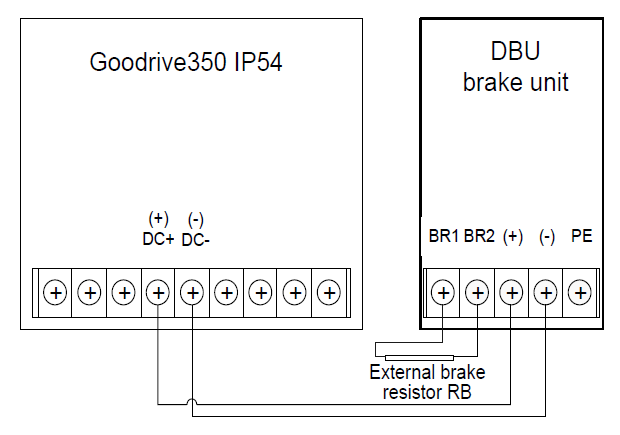
Installation of brake units
|
|

The following figure shows the connection of one VFD to a dynamic brake unit.