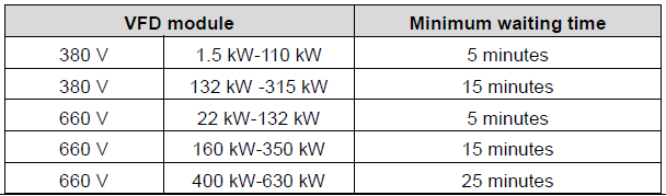
| Only qualified electricians are allowed to operate on the VFD. Do not carry out any wiring and inspection or changing components when the power supply is applied. Ensure all input power supply is disconnected before wiring and checking and always wait for at least the time designated on the VFD or until the DC bus voltage is less than 36 V. Below is the table of the waiting time:
|
| Do not refit the VFD unless authorized; otherwise fire, electric shock or other injury may occur. |
| The base of the radiator may become hot during running. Do not touch to avoid hurt. |
| The electrical parts and components inside the VFD are electrostatic. Take measurements to avoid electrostatic discharge during relevant operation. |


1.4.1 Delivery and installation
| Please install the VFD on fire-retardant material and keep the VFD away from combustible materials. Connect the brake optional parts (brake resistors, brake units or feedback units) according to the wiring diagram. Do not operate on the VFD if there is any damage or components loss to the VFD. Do not touch the VFD with wet items or your body, otherwise electric shock may occur. |

Note:
Select appropriate moving and installing tools to ensure a safe and normal running of the VFD and avoid physical injury or death. For physical safety, the erector should take some mechanical protective measurements, such as wearing exposure shoes and working uniforms.
Ensure to avoid physical shock or vibration during delivery and installation.
Do not carry the VFD by its cover. The cover may fall off.
Install away from children and other public places.
The VFD cannot meet the requirements of low voltage protection in IEC61800-5-1 if the altitude of installation site is above 2000m.
Please use the VFD on appropriate condition (See section 4.2.1 "Installation environment" for detailed information).
Don't allow screws, cables and other conductive items to fall inside the VFD.
The leakage current of the VFD may be larger than 3.5 mA during operation. Perform reliable grounding and ensure that the grounding resistance is lower than 10 Ω. The conductivity of the PE grounding conductor is the same as that of the phase conductor. For models higher than 30 kW, the cross sectional area of the PE grounding conductor can be slightly less than the recommended area.
R, S and T are the input terminals of the power supply, while U, V and W are the motor terminals. Please connect the input power cables and motor cables with proper techniques; otherwise the damage to the VFD may occur.
| Disconnect all power supplies applied to the VFD before the terminal wiring and wait for at least the designated time after disconnecting the power supply. High voltage is present inside the VFD during running. Do not carry out any operation except for the keypad setting. It must be noted that the control terminals of the VFDs of 3PH AC 500V and 3PH AC 660V are ELV (Extra Low Voltage) circuit, which cannot be connected directly to the accessible terminals of other devices if no protective isolation measure is taken. Control terminals of products -5 and -6 are ELV (Extra Low Voltage) circuits. Without protection insulation, you need to avoid directly connecting control terminals to accessible terminals of other devices. The VFD may start up by itself when P01.21=1. Do not get close to the VFD and motor. The VFD cannot be used as "Emergency-stop device". The VFD cannot be used to break the motor suddenly. A mechanical brake device should be provided. Besides the above items, check to ensure the following ones before the installation and maintenance during the running of the permanent synchronization motor: 1. All input power supply is disconnected (including the main power supply and the control power supply). 2. The permanent magnet synchronization motor has stopped running and measured to ensure the output voltage of the VFD is less than 36 V. 3. The waiting time of the permanent magnet synchronization motor after stopping is no less than the time designated and measure to ensure the voltage between + and – is less than 36 V. 4. Ensure the permanent magnet synchronization motor does not rotate again because of the external load. It is recommended to install effectively external brake devices or disconnect the electric wiring between the motor and the VFD directly. |

Note:
Do not switch on or off the input power supply of the VFD frequently.
For VFDs that have been stored for a long time, check and fix the capacitance and try to run it again before utilization (seeChapter 9"Routine maintenance").
Cover the front board before running, otherwise electric shock may occur.
1.4.3 Maintenance and replacement of components
| Only qualified electricians are allowed to perform the maintenance, inspection, and components replacement of the VFD. Disconnect all power supplies to the VFD before the terminal wiring. Wait for at least the time designated on the VFD after disconnection. Take measures to avoid screws, cables and other conductive matters to fall into the VFD during maintenance and component replacement. |

Note:
Please select proper torque to tighten screws.
Keep the VFD, parts and components away from combustible materials during maintenance and component replacement.
Do not carry out any isolation and pressure test on the VFD and do not measure the control circuit of the VFD by megameter.
Carry out a sound anti-electrostatic protection to the VFD and its internal components during maintenance and component replacement.
| There are heavy metals in the VFD. Deal with it as industrial waste. |
| When the life cycle ends, the product should enter the recycling system. Dispose of it separately at an appropriate collection point instead of placing it in the normal waste stream. |