Function code | Name | Detailed instruction of parameters | Default value | Modify |
P08.00 | ACC time 2 | For detailed definition, see the description of P00.11 and P00.12. Four groups of ACC and DEC time are defined for the Goodrive35 series. You can set the ACC and DEC time through the corresponding multi-function digital input terminals (in the P05 group). For the Goodrive35 series VFD, the default setting is the first group of ACC and DEC time. Setting range: 0.0–3600.0s | Depend on model | ○ |
P08.01 | DEC time 2 | Depend on model | ○ | |
P08.02 | ACC time 3 | Depend on model | ○ | |
P08.03 | DEC time 3 | Depend on model | ○ | |
P08.04 | ACC time 4 | Depend on model | ○ | |
P08.05 | DEC time 4 | Depend on model | ○ | |
P08.06 | Jogging frequency | This parameter is used to set the reference frequency of the VFD during jogging. Setting range: 0.00 Hz–P00.03 (max. output frequency) | 5.00 Hz | ○ |
P08.07 | Jogging ACC time | P08.07 indicates the time the VFD takes to accelerate from 0 Hz to P00.03 (max. output frequency). P08.08 indicates the time the VFD takes to decelerate from P00.03 (max. output frequency) to 0 Hz. Setting range: 0.0–3600.0s | Depend on model | ○ |
P08.08 | Jogging DEC time | Depend on model | ○ | |
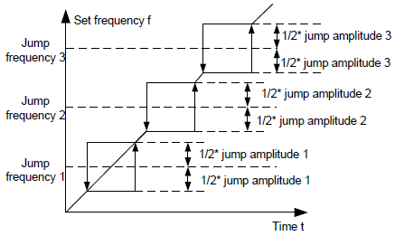
P08.09 | Jumping frequency 1 | When the set frequency is in the range of jumping frequency, the VFD will run at the edge of the jumping frequency. The VFD can avoid the mechanical resonance point by setting the jumping frequency. The VFD can set three jumping frequency. But this function will be invalid if all jumping points are 0.
Setting range: 0.00 Hz–P00.03 (max. output frequency) | 0.00 Hz | ○ |
P08.10 | Jumping frequency range 1 | 0.00 Hz | ○ | |
P08.11 | Jumping frequency 2 | 0.00 Hz | ○ | |
P08.12 | Jumping frequency range 2 | 0.00 Hz | ○ | |
P08.13 | Jumping frequency 3 | 0.00 Hz | ○ | |
P08.14 | Jumping frequency range 3 | 0.00 Hz | ○ | |
P08.15 | Overvoltage stall modulator gain | Setting range: 0.0–1000.0 | 12.0 | ○ |
P08.16 | ASR differential gain | Setting range: 0.00–10.00s | 0.00 s | ○ |
P08.17 | Max torque of inertia compensation | Limit the max. inertia compensation torque to prevent the inertia compensation torque from being too large. Setting range: 0.0–150.0% (rated torque of the motor) | 20.0% | ○ |
P08.18 | Inertia compensation filter times | Filter times of inertia compensation torque is used to smooth the inertia compensation torque. Setting range: 0–10 | 7 | ○ |
P08.19 | High-frequency ACR proportional coefficient | In the closed-loop vector control mode (P00.00=3), when the running frequency is lower than the ACR high frequency switching point (P08.21), the ACR PI parameters are P03.09 and P03.10; and when the running frequency is higher than the ACR high frequency switching point, the ACR PI parameters are P08.19 and P08.20. Setting range of P08.19: 0–20000 Setting range of P08.20: 0–20000 Setting range of P08.21: 0.0–100.0% (relative max frequency) | 1000 | ○ |
P08.20 | High-frequency ACR integral coefficient | 1000 | ○ | |
P08.21 | ACR high frequency switching point | 100.0% | ○ | |
P08.22 | Inertia identification torque | Because of the friction, it is necessary to set identification torque for normal inertia identification. 0.0–100.0% (rated torque of the motor) | 10.0% | ◎ |
P08.23 | Inertia identification | 0: No operation 1: Starting identification: press "RUN" to enter into the program after starting identification until display "-END-"; the identified system inertia is saved in P08.24. | 0 | ◎ |
P08.24 | System inertia | The identified system inertia can be set manually when the system inertia is known. The displayed system inertia may be less than 0.001kgm2 for the motors below 1 kW. Setting range: 0.000–30.000 kgm2 | 0.000 kgm2 | ○ |
P08.25 | Inertia compensation enabled | Identifying the system inertia correctly and enabling the inertia compensation can improve the dynamic response of the system. 0: Enabled 1: Disabled | 0 | ○ |
P08.26 | Stopping protection for undervoltage | Ones: Enabling 0: Disabled 1: Enabled Tens: Voltage selection 0: Internal setting 1: P8.27 setting After the valid undervoltage stopping, the VFD will decelerate to stop according to the DEC time set by P08.05. | 0x00 | ○ |
P08.27 | Stopping voltage for undervoltage | Setting range: 250.0–1000.0 V | 450.0 V | ○ |
P08.28 | Automatic fault reset times | Automatic fault reset times: When the VFD selects automatic fault reset, it is used to set the times of automatic reset, if the continuous reset times exceeds the value set by P08.28, the VFD will report fault and stop to wait for repair. Interval of automatic fault reset: Select the interval time from when fault occurred to automatic fault reset actions. After VFD starts, if no fault occurred during 60s, the fault reset times will be zeroed out. Setting range of P08.28: 0–10 Setting range of P08.29: 0.1–3600.0s | 0 | ○ |
P08.29 | Interval time of automatic fault reset | 1.0 s | ○ | |
P08.30 | Frequency decreasing ratio of the dropping control | The output frequency of the VFD changes as the load. And it is mainly used to balance the power when several VFDs drive one load. Setting range: 0.00–50.00 Hz | 0.00 Hz | ○ |
P08.31 | Motor shifting | Goodrive35 supports the shift between two motors. This function is used to select the shifting channel. LED ones: shifting channel 0: Terminal shifting; digital terminal is 35 1: Modbus communication shifting 2: PROFIBUS/CANopen communication shifting | 0 | ◎ |
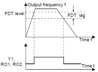
P08.32 | FDT1 electrical level detection value | When the output frequency exceeds the corresponding frequency of FDT electrical level, the multi-function digital output terminals will output the signal of "frequency level detect FDT" until the output frequency decreases to a value lower than (FDT electrical level—FDT retention detection value) the corresponding frequency, the signal is invalid. Below is the waveform diagram:
Setting range of P08.32: 0.00 Hz–P00.03 (max. output frequency) Setting range of P08.33: -200.0–100.0% (FDT1 electrical level) Setting range of P08.34: 0.00 Hz–P00.03 (max. output frequency) Setting range of P08.35: -200.0–100.0% (FDT2 electrical level) | 50.00 Hz | ○ |
P08.33 | FDT1 retention detection value | 5.0% | ○ | |
P08.34 | FDT2 electrical level detection value | 50.00 Hz | ○ | |
P08.35 | FDT2 retention detection value | 5.0% | ○ | |
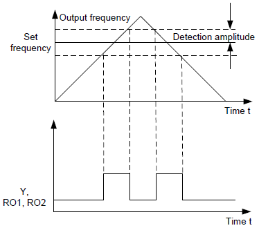
P08.36 | Amplitude value for frequency arrival detection | When the output frequency is among the positive or negative detection range of the set frequency, the multi-function digital output terminal will output the signal of "frequency arrival", see the diagram below for detailed information:
The setting range: 0.00 Hz–P00.03 (max. output frequency) | 0.00 Hz | ○ |
P08.37 | Energy brake enable | This parameter is used to control the internal brake pipe inside the VFD. 0: Disable 1: Enable Note: Only applied to internal brake pipe. | 1 | ○ |
P08.38 | Threshold voltage of dynamic brake | Set the starting bus voltage of dynamic brake, adjust this value properly to brake the load effectively. The default value changes with voltage level Setting range: 200.0–2000.0 V | 380 V voltage: 700.0 V | ○ |
660 V voltage: 1120.0 V | ||||
P08.39 | Cooling fan running mode | 0: Normal mode 1: The fan keeps running after power on | 0 | ○ |
P08.40 | PWM selection | 0x000–0x111 LED ones: PWM mode setting 0: PWM mode 1, 3PH and 2PH modulation 1: PWM mode 2, 3PH modulation LED tens: Low-speed carrier frequency limiting mode 0: Reducing the carrier frequency at low speed, limiting the carrier frequency to 4 kHz when the machine runs at low speed. This mode is valid only for the closed-loop vector mode (P00.00=3). 1: No reducing the carrier frequency at low speed Hundreds place: Dead-zone compensation method setting 0: Method 1 1: Method 2 | 0x001 | ◎ |
P08.41 | Overmodulation | 0x00–0x91 Ones: Overmodulation selection 0: Invalid 1: Valid Tens: Heavy overmodulation factor 0–9 | 0x01 | ◎ |
P08.42 | Keypad data control | 0x000–0x1223 LED ones: Frequency enable selection 0: Both ∧/∨ keys and digital potentiometer adjustments are valid 1: Only ∧/∨ keys adjustment is valid 2: Only digital potentiometer adjustments is valid 3: Neither ∧/∨ keys nor digital potentiometer adjustments are valid LED tens: Frequency control selection 0: Only valid when P00.06=0 or P00.07=0 1: Valid for all frequency setting manner 2: Invalid for multi-step speed when multi-step speed has the priority LED hundreds: Action selection during stopping 0: Setting is valid 1: Valid during running, cleared after stopping 2: Valid during running, cleared after receiving the stop command LED thousands: ∧/∨ keys and digital potentiometer integral function 0: The integral function is valid 1: The integral function is invalid | 0x0000 | ○ |
P08.43 | Integral ratio of keypad potentiometer | 0.01–10.00 s | 0.10 Hz/s | ○ |
P08.44 | UP/DOWN terminals control | 0x000–0x221 LED ones: frequency control selection 0: UP/DOWN terminals setting valid 1: UP/DOWN terminals setting valid LED tens: frequency control selection 0: Only valid when P00.06=0 or P00.07=0 1: All frequency means are valid 2: When the multi-step are priority, it is invalid to the multi-step LED hundreds: action selection when stop 0: Setting valid 1: Valid in the running, clear after stop 2: Valid in the running, clear after receiving the stop commands | 0x000 | ○ |
P08.45 | UP terminals frequency changing ratio | 0.01–50.00 Hz/s | 0.50 Hz/s | ○ |
P08.46 | DOWN terminals frequency changing ratio | 0.01–50.00 Hz/s | 0.50 Hz/s | ○ |
P08.47 | Frequency setting at power loss | 0x000–0x121 LED ones: Action selection when power off. 0: Save when power off 1: Clear when power off LED tens: Action selection when Modbus set frequency off 0: Save when power off 1: Clear when power off 2: Clear when stop LED hundreds: The action selection when other frequency set frequency off 0: Save when power off 1: Clear when power off | 0x000 | ○ |
P08.48 | MSB of initial power consumption | This parameter is used to set the original value of the power consumption. The original value of the power consumption =P08.48*1000+ P08.49 Setting range of P08.48: 0–59999 kWh (k) Setting range of P08.49: 0.0–999.9 kWh | 0° | ○ |
P08.49 | LSB of initial power consumption | 0.0° | ○ | |
P08.50 | Magnetic flux brake | This function code is used to enable magnetic flux. 0: Invalid. 100–150: The bigger the coefficient, the stronger the brake is. This VFD is used to increase the magnetic flux to decelerate the motor. The energy generated by the motor during brake can be converted into heat energy by increasing the magnetic flux. The VFD monitors the state of the motor continuously even during the magnetic flux period. So the magnetic flux can be used in the motor stop, as well as to change the rotation speed of the motor. Its other advantages are: Brake immediately after the stop command. It does not need to wait the magnetic flux weaken. Better cooling for motors. The current of the stator other than the rotor increases during magnetic flux brake, while the cooling of the stator is more effective than the rotor. | 0 | ● |
P08.51 | Current regulation coefficient on input side | This function code is used to adjust the displayed current of the AC input side. Setting range: 0.00–1.00 | 0.56 | ○ |