Function code | Name | Detailed instruction of parameters | Default value | Modify |
P17.00 | Setting frequency | Display current set frequency of the VFD Range: 0.00 Hz–P00.03 | 0.00 Hz | ● |
P17.01 | Output frequency | Display current output frequency of the VFD Range: 0.00 Hz–P00.03 | 0.00 Hz | ● |
P17.02 | Ramp reference frequency | Display current ramp reference frequency of the VFD Range: 0.00 Hz–P00.03 | 0.00 Hz | ● |
P17.03 | Output voltage | Display current output voltage of the VFD Range: 0–1200 V | 0 V | ● |
P17.04 | Output current | Display present output current of the VFD Range: 0.0–5000.0 A | 0.0 A | ● |
P17.05 | Motor speed | Display the rotation speed of the motor. Range: 0–65535 RPM | 0 RPM | ● |
P17.06 | Torque current | Display present torque current of the VFD Range: -3000.0–3000.0 A | 0.0 A | ● |
P17.07 | Exciting current | Display present exciting current of the VFD Range: -3000.0–3000.0 A | 0.0 A | ● |
P17.08 | Motor power | Display present power of the motor. Setting range: -300.0%–300.0% (rated power of the motor) | 0.0% | ● |
P17.09 | Output torque | Display the current output torque of the VFD; 100% relative to rated torque of the motor. During forward running, the positive value is the motoring state while the negative value is generating state. During reverse running, the positive value is the generating state while the negative value is the motoring state. Range: -250.0–250.0% | 0.0% | ● |
P17.10 | Evaluated motor frequency | Evaluate the motor rotor frequency on closed-loop vector Range: 0.00–P00.03 | 0.00 Hz | ● |
P17.11 | DC bus voltage | Display current DC bus voltage of the VFD. Range: 0.0–2000.0 V | 0.0 V | ● |
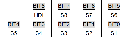
P17.12 | Digital input terminals state | Display present digital input terminals state of the VFD.
Range: 0000–01FF | 0 | ● |
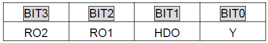
P17.13 | Digital output terminals state | Display present digital output terminals state of the VFD.
Range: 0000–000F | 0 | ● |
P17.14 | Digital adjustment | Display the adjustment via the VFD keypad Range : 0.00 Hz–P00.03 | 0.00 Hz | ● |
P17.15 | Torque reference | Display the torque given, the percentage to the current rated torque of the motor. Setting range: -300.0%–300.0% (rated current of the motor) | 0.0% | ● |
P17.16 | AI1 adjustment voltage | Display A1 adjustment voltage. 0.00–10.00 V | 0.00 V | ● |
P17.17 | AI2 adjustment voltage | Display A2 adjustment voltage. 0.00–10.00 V | 0.00 V | ● |
P17.18 | AI3 adjustment voltage | Display A3 adjustment voltage. 0.00–10.00 V | 0.00 V | ● |
P17.19 | AI1 input voltage | Display analog AI1 input signal Range: 0.00–10.00 V | 0.00 V | ● |
P17.20 | AI2 input voltage | Display analog AI2 input signal Range: 0.00–10.00 V | 0.00 V | ● |
P17.21 | AI3 input voltage | Display analog AI3 input signal Range: -10.00–10.00 V | 0.00 V | ● |
P17.22 | HDI input frequency | Display HDI input frequency Range: 0.00–50.00 kHz | 0.00 kHz | ● |
P17.23 | PID reference | Display PID reference value. Range: -100.0–100.0% | 0.0% | ● |
P17.24 | PID feedback | Display PID feedback value Range: -100.0–100.0% | 0.0% | ● |
P17.25 | Power factor of the motor | Display the current power factor of the motor. Range: -1.00–1.00 | 0.00 | ● |
P17.26 | Current running time | Display the current running time of the VFD. Range: 0–65535 min | 0 min | ● |
P17.27 | Simple PLC and the current step of the multi-step speed | Display simple PLC and the current stage of the multi-step speed Range: 0–15 | 0 | ● |
P17.28 | ASR controller output | This parameter is used to display the output value of the automatic speed regulator (ASR). The value is relative to the rated torque of the motor. Range: -300.0%–+300.0% (the rated torque of the motor) | 0.0% | ● |
P17.29 | Initial identification angle of synchronous machine | Display initial identification angle of synchronous machine Range: 0.0–359.9 | 0.0 | ● |
P17.30 | Phase compensation of SM | Display SM phase compensation Range: -180.0–180.0 | 0.0 | ● |
P17.31 | Reserved | |||
P17.32 | Reserved | |||
P17.33 | Exciting current reference | Display the exciting current reference in the vector control mode Range: -3000.0–3000.0 A | 0.0 A | ● |
P17.34 | Torque current reference | Display the torque current reference in the vector control mode Range: -3000.0–3000.0 A | 0.0 A | ● |
P17.35 | AC current | Display the value of inlet current in AC side Range: 0.0–5000.0 A | 0.0 A | ● |
P17.36 | Output torque | Display the output torque value. During forward running, the positive value is the motoring state while the negative value is generating state. During reverse running, the positive value is the generating state while the negative value is the motoring state. Range : -3000.0Nm–3000.0 Nm | 0.0 Nm | ● |
P17.37 | PID deviation | -100.0%–100.0% | 0.0% | ● |
P17.38 | PID output | -200.00%–200.00% | 0.00% | ● |
P17.39 | Wrong download of parameters | 0.00–29.00 | 0.00 | ● |