1. Differential output (suitable toC1, H1 and H2)
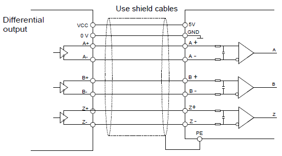
Note: The diagram of differential output is given to the H1 interface, C1 interface applies opto-isolator and H2 interface applies differential chips. The external wiring is the same as that of H1.
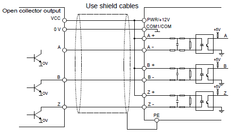
2. Open collector output (suitable to C1 and H1)
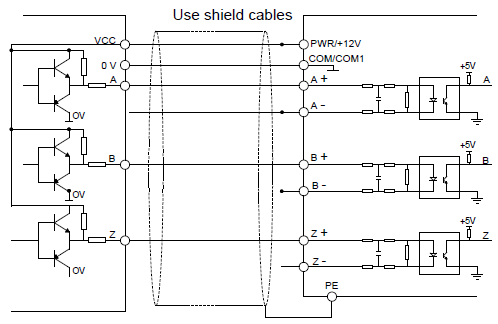
3. Complementary output (suitable to C1 and H1)
Note:
Above diagram are given to the features of common encoder and suitable to H1 interface.
The diagram of differential output is given to the H1 interface, C1 interface applies opto-isolator and H2 interface applies differential chips. The external wiring is the same as that of H1.
If the external current is limited, C1and H1 interface is suitable to encoder signal and pulse reference signal input with greater voltage.
4. Push-pull output encoder connection
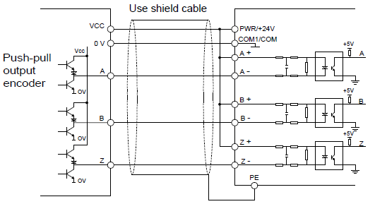
Push-pull output mode wiring diagram 1
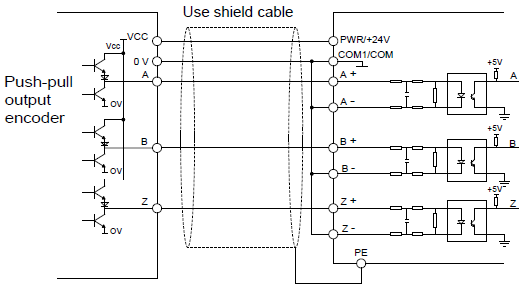
Push-pull output mode wiring diagram 2
Note: When this output mode is used, please refer to the electrical specifications of output current in the encoder manual.
1. If the flowing–in current of the output current is more than 25mA and the flowing-out current is less than 25mA and , please apply mode 1
2. If the flowing-in current of the output current is less than 25mA and the flowing–out current is more than 25mA, please apply mode 2
3. If the flowing-in and flowing–out current of the output current are more than 25mA, please apply mode 1 or 2.
Note: Z signal is needed for the spindle positioning VFD and the wiring is the same as that of A and B signal.
1. Closed-loop vector debugging of AM
(1) Set P00.18=1 and restore to the factory settings.
(2) Set the parameters of P00.03, P00.04 and P02 group
(3) Motor autotuning
a) Set P00.15=1 and begin rotating autotuning
b) Set P00.15=2 and begin static autotuning
De-couple the load from the motor to carry out rotating autotuning; otherwise, carry out static autotuning. The parameters after autotuning can be saved in P02 group automatically.
(4) Check the encoder is installed and correctly set
a) Ensure the encoder direction and parameters setting
Set P20.01 and set P00.00=2, P00.10=20 Hz. Start the VFD and watch the value of P18.00. If the value is negative, the direction of the encoder is reversed and it is necessary to set P20.02=1, if a huge bias exists, then the set value of P20.01 is wrong. Check if the fluctuation of P18.02 exists, then the set value of P20.01 is wrong and check the wiring and the shield layer.
b) Ensure the direction of pulse Z
Set P00.10=20 Hz and P00.13 and observe the offset of P18.02 to ensure the value is less than 5. If the reverse function of pulse Z are not available after setting P20.02, then exchange A and B phase of the encoder after power off. And then observe the rotating value of P18.02 to ensure how far the forward value derivate from the reverse value. The direction of pulse Z only impacts the positioning accuracy of forward/reverse rotating if pulse Z is applied in the spindle positioning.
(5) Trial running of the closed-loop vector
Set P00.00=3 to carry out closed-loop vector control. Adjust P00.10 and the ASR and ACR PI parameters in the P03 group to ensure the smooth running.
(6) The weak magnetism control
Set P03.26=0–2000 and observe the weak magnetism control. Adjust P03.22–P03.24 according the actual need.
2. Closed-loop vector debugging of SM
(1) Set P00.18=1 and restore to the factory settings.
(2) Set P00.03=3, P00.03, P00.04 and the parameters in P02 group.
(3) Set P20.00 and P20.01.
If rotary transformer encoder is selected, please set the pulse pair of the encoder (the number of pole pair*1024), if the pole pair is 4, please set P20.01=4096.
(4) Check the encoder is installed and correctly set.
Observe the value of P18.21 after motor stopping to ensure the value has no fluctuations or small fluctuations. But check the wiring and grounding if the fluctuation is huge. Rotate the motor slowly and the value of P18.21 may change slowly, too. If the value of P18.02 does not change and not equal to 0 after several cycles, then the signal of encoder Z is correct.
(5) Autotuning of the pole initial angle
Set P20.11=1 or 2 (1 is the rotating autotuning and 2 is the static autotuning) and press "RUN".
a) Rotating autotuning (P20.11=1)
Detect the pole position in the beginning, and then accelerate to 10 Hz to autotune the pole position of pulse Z, after that decelerate to stop.
If ENC1O or ENC1D occurs during the operation, please set P20.02=1 and then re-autotune. If ENC1Z occurs, check the connection of pulse Z.
The result will be saved in P20.09 and P20.10 after autotuning.
b) Static autotuning
It is recommended to apply rotating autotuning P20.11=1 to get higher autotuning precision if the load can be de-coupled. The other autotuning mode is also available if the load cannot de-couple. The pole position after autotuning is saved in P20.09 and P20.10.
(6) Trial running of the closed-loop vector
Adjust P0.10 and the ASR and ACR PI parameters in P3 group to ensure the smooth running. If fluctuation occurs, reduce the value of P03.00 and P03.03, and P03.09 and P03.10. If the current fluctuates at low speed, adjust P20.05.
Note: Reset P20.02 after change the motor or encoder wiring and re-autotune the angle of pulse Z.
3. Debugging steps of pulse string control
Pulse input is based on closed-loop vector control and speed detection is applied in the subsequent steps.
(1) Set P00.18=1 and restore to the factory settings.
(2) Set P00.03 and P0.04 and the parameters in P02 group.
(3) Motor autotuning: rotating autotuning and static autotuning.
(4) Check the encoder is installed and correctly set. Set P00.00=3 and P00.10=20 Hz and operate. Check the control and performance of the system.
(5)Set P21.00=0001 and select the position control as the position mode. There are 4 pulse command modes which can be selected by P21.01.
In the position mode, the user can select the high/LSB of the reference and feedback value, P18.02, P18.00, P18.17, P18.19 and the relationship between P18.08 and P18.02, P18.17, P18.18 and P18.19.
(6) P21.02 and P21.03 can be shifted through speed command, torque command and terminal operation.
(7) If set P21.08 to 0, the position control is invalid, the pulse train is the frequency source and P21.13 is 100%. The deceleration and acceleration time are determined by the deceleration and acceleration time of the pulse train, but the deceleration and acceleration time of the pulse train in the system can be adjusted. If the pulse train is selected to control the speed, set P21.00=0000, P00.06 or P00.07=12, AB pulse train, then the acceleration and deceleration time depend on the time of the VFD and the parameter setting is determined by P21. In speed control mode, set the filter time of AB pulse by P21.29.
(8)The input frequency of the pulse train is the same as the feedback frequency of the encoder pulse. The relationship between them can be changed by modifying P21.11 and P21.12.
(9)When run command or servo enable is valid by setting P21.00 or terminal function 63, the VFD will run into the pulse string servo mode.
4. Debugging steps of spindle positioning
The spindle positioning is the function of stopping such as zeroing and scaling on the basis of closed-loop vector control.
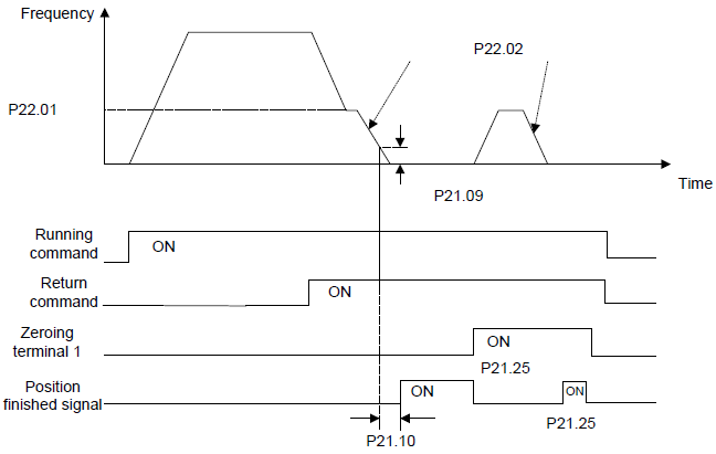
The steps of (1)–(4) are the same as the 4 steps in close-loop vector control mode. The function of spindle positioning is available in the position control mode and speed control mode.
(5) Set P22.00.bit0=1 and P22.00.bit1. If the system applies encoder to detect the speed, set P22.00.bit1=0, and if the system applies the photoelectric switch to detect the speed, set P22.00.bit1=1; set P22.00.bit2, P22.00.bit3 and P22.00.bit7
(6)Spindle zeroing
a) Set P22.00.bit4 to select the positioning direction.
b) There are 4 zero positions in P22 group. Set P05 to select the zeroing position. Operation on P18.10 can watch the stopping state.
c) The positioning length is determined by the deceleration time and the deceleration speed.
(7) Spindle scaling
There are 7 scale positions in P22 group. Set P05 to select the scale position. Enable corresponding terminal after motor stopping, the motor will inquiry the scaling state and turn to corresponding position. Operation on P18.09 can watch the state.
(8) Priority of the speed control, position control, zeroing and scaling
The priority of speed control > The priority of scaling. If the system runs at the scaling mode, when the spindle positioning is disabled, the motor will runs at the speed mode or position mode.
The priority of zeroing > The priority of scaling. The scaling commands are valid if the scaling terminal is turning from 000state to non-000state. If 000–011, then the spindle will operate scaling 3, the transition time of terminal switching is less than 10 ms, otherwise wrong scaling command may be carried out.
(9) Positioning retention
In positioning, the gain of position loop is P21.03, but when the positioning is finished, it is P21.02. Adjust P03.00, P03.01, P20.05 and P21.02 to keep the position and stabilize the system.
(10) Positioning command (bit6 of P22.00)
Signal of electrical level: Positioning command can only be executed after operation command or servo enable.
(11) Spindle reference selection (bit0 of P22.00)
Below positioning modes are available in encoder pulse Z positioning:
a) The encoder is installed on the motor shaft and the shaft is rigid-connected to the spindle with the ratio of 1: 1.
b) The encoder is installed on the motor shaft and the shaft is connected to the spindle by belt with the ratio of 1: 1.
It is recommended to begin positioning at the area close to the switch because the belt may slide when the spindle rotates at a high speed to cause inaccurate positioning.
c) The encoder is installed on the spindle and the motor shaft is connected to the spindle by belt. The drive ratio cannot be 1: 1.
It is necessary to set P20.06 and set P22.14 to be 1. The control performance of closed-loop vector may be affected if the encoder is not installed on the motor.
Below spindle positioning mode is available:
d) The encoder is installed on the motor shaft. The drive ratio cannot be 1: 1.
It is necessary to set P22.14 at the same time.
5. Digital positioning
The figure is shown as below:
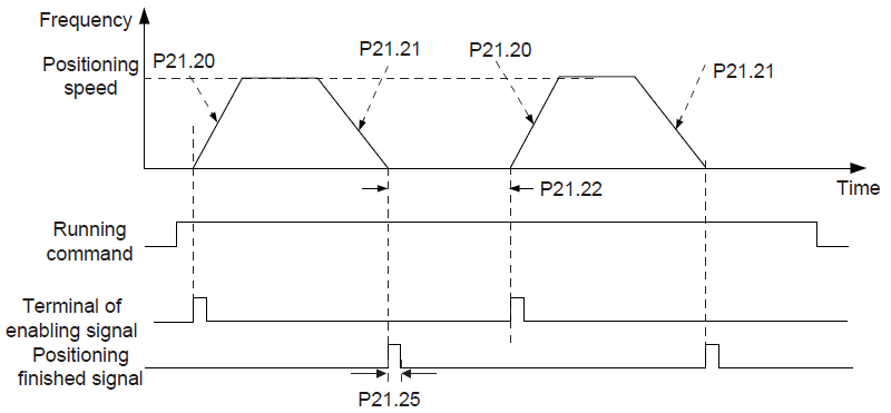
The steps of (1)–(4) are the same as the 4 steps in close-loop vector control mode. After the 4 steps, the control requirements can be met.
(5) Set P21.00=0011 and set P21.17, P21.11, P21.12, P21.18, P21.19, P21.20 and P21.21 according to actual needs.
(6) Single positioning operation
Set P21.16.bit1=0, and the motor will set as step (5) and keep on the positioning place.
(7) Cycle positioning operation
Set P21.16.bit1=1 to enable the loop positioning which includes continuous mode and repeated mode. The operation is also available by terminals function.
6. Photoelectric switch positioning
Photoelectric switch positioning is to position in the closed-loop vector control mode.
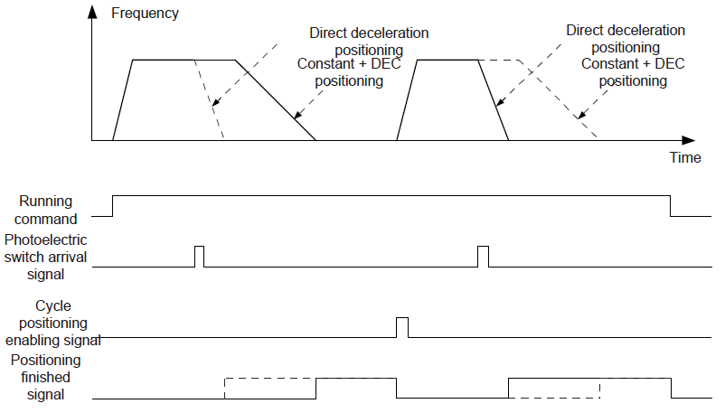
The steps of (1)–(4) are the same as the 4 steps in close-loop vector control mode. After the 4 steps, the control requirements can be met.
(5) Set P21.00=0021 to enable the positioning. The signal is only connected with S8. Set P05.08=43 and P21.17, P21.11, P21.12 and P21.21. If the operation speed is big or the setting placement is too small, the positioning deceleration time is invalid and it will enter into the direct deceleration mode.
(6) Cycle positioning operation
The motor will keep on the current position after positioning. Set group P05. If the terminal receives the enabling signal, the motor will operate at the setting speed in speed mode, after receiving photoelectric switch signal, it will position again.
(7) Positioning retention
During the positioning, the position loop gain is P21.03, but after positioning, it is P21.02. Adjust P03.00, P03.01, P20.05 and P21.02 to keep the position and avoid vibration.