The Modbus protocol of the VFD is RTU mode and the physical layer is RS485.
The interface of RS485 works on semiduplex and its data signal applies differential transmission which is called balance transmission, too. It uses twisted pairs, one of which is defined as A (+) and the other is defined as B (-). Generally, if the positive electrical level between sending drive A and B is among +2–+6 V, it is logic"1", if the electrical level is among -2 V–-6 V, it is logic"0".
485+ on the terminal board corresponds to A and 485- to B.
Communication baud rate means the binary bit number in one second. The unit is bit/s (bps). Higher the baud rate is, quicker the transmission speed is, and weaker the anti-interference is. If twisted pair of 0.56mm (24AWG) is used as communication cable, the max transmission distance is as below:
Baud rate | Max transmission distance | Baud rate | Max transmission distance |
2400BPS | 1800m | 9600BPS | 800m |
4800BPS | 1200m | 19200BPS | 600m |
It is recommended to use shield cables and make the shield layer as the grounding wires during RS485 remote communication.
In the cases with less devices and shorter distance, it is recommended to use 120Ω terminal resistor as the performance will be weakened if the distance increases even if the network can perform well without load resistor.
10.3.1.1 Single application
Figure 10‑1 is the site Modbus connection figure of single VFD and PC. Generally, the computer does not have RS485 interface, the RS232 or USB interface of the computer should be converted into RS485 by converter. Connect the A terminal of RS485 to the 485+ terminal of the VFD and B to the 485- terminal. It is recommended to use the shield twisted pairs. When applying RS232-RS485 converter, if the RS232 interface of the computer is connected to the RS232 interface of the converter, the wire length should be as short as possible within the length of 15m. It is recommended to connect the RS232-RS485 converter to the computer directly. If using USB-RS485 converter, the wire should be as short as possible, too.
Select a right interface to the upper monitor of the computer (select the interface of RS232-RS485 converter, such as COM1) after the wiring and set the basic parameters such as communication baud rate and digital check bit to the same as the VFD.
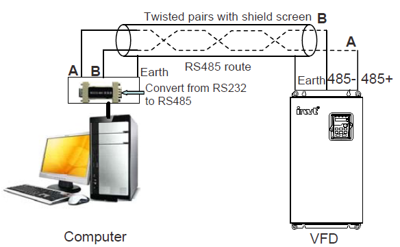
Figure 10‑1 RS485 physical connection in single application
10.3.1.2 Multi-application
In the real multi-application, the chrysanthemum connection and star connection are commonly used.
Chrysanthemum chain connection is required in the RS485 industrial fieldbus standards. The two ends are connected to terminal resistors of 120Ω which is shown as Figure 10‑2. Figure 10‑3 is the simply connection figure and Figure 10‑4 is the real application figure.
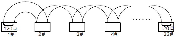
Figure 10‑2 Chrysanthemum connection
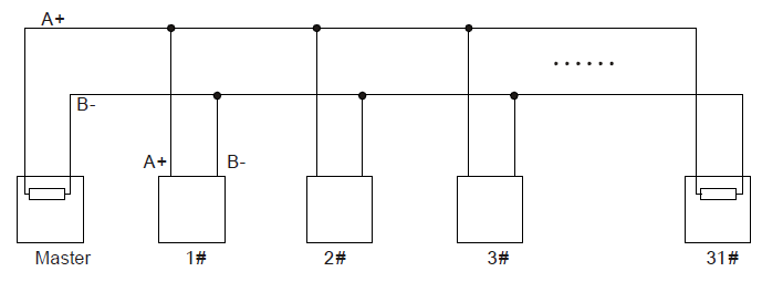
Figure 10‑3 Chrysanthemum connection
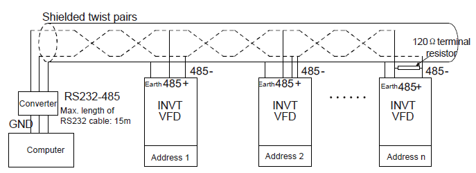
Figure 10‑4 Chrysanthemum connection applications
Figure 10‑5 is the star connection. Terminal resistor should be connected to the two devices which have the longest distance. (1# and 15#device)
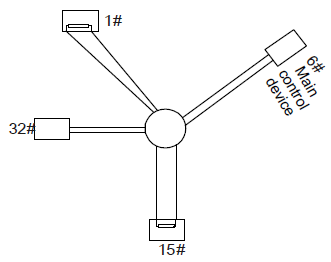
Figure 10‑5 Star connection
It is recommended to use shield cables in multiple connection. The basic parameter of the devices, such as baud rate and digital check bit in RS485 should be the same and there should be no repeated address.
10.3.2.1 RTU communication frame format
If the controller is set to communicate by RTU mode in Modbus network every 8bit byte in the message includes two 4Bit hex characters. Compared with ACSII mode, this mode can send more data at the same baud rate.
Code system
1 start bit
7 or 8 digital bit, the minimum valid bit can be sent firstly. Every 8 bit frame includes two hex characters (0...9, A...F)
1 even/odd check bit. If there is no checkout, the even/odd check bit is inexistent.
1 end bit (with checkout), 2 bit (no checkout)
Error detection field
CRC
The data format is illustrated as below:
11-bit character frame (BIT1–BIT8 are the data bits)
Start bit | BIT1 | BIT2 | BIT3 | BIT4 | BIT5 | BIT6 | BIT7 | BIT8 | Check bit | End bit |
10-bit character frame (BIT1–BIT7 are the data bits)
Start bit | BIT1 | BIT2 | BIT3 | BIT4 | BIT5 | BIT6 | BIT7 | Check bit | End bit |
In a character frame, only the data bits carry information. The start bit, check bit, and end bit are used to facilitate the transmission of the data bits to the destination device. In practical applications, you must set the data bits, parity check bits, and end bits consistently.
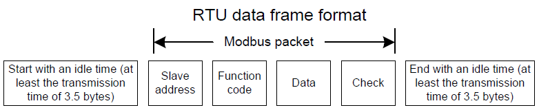
In RTU mode, the transmission of a new frame always starts from an idle time (the transmission time of 3.5 bytes). On a network where the transmission rate is calculated based on the baud rate, the transmission time of 3.5 bytes can be easily obtained. After the idle time ends, the data domains are transmitted in the following sequence: slave address, operation command code, data, and CRC check character. Each byte transmitted in each domain includes 2 hexadecimal characters (0–9, A–F). The network devices always monitor the communication bus. After receiving the first domain (address information), each network device identifies the byte. After the last byte is transmitted, a similar transmission interval (the transmission time of 3.5 bytes) is used to indicate that the transmission of the frame ends. Then, the transmission of a new frame starts.
The information of a frame must be transmitted in a continuous data flow. If there is an interval greater than the transmission time of 1.5 bytes before the transmission of the entire frame is complete, the receiving device deletes the incomplete information, and mistakes the subsequent byte for the address domain of a new frame. Similarly, if the transmission interval between two frames is shorter than the transmission time of 3.5 bytes, the receiving device mistakes it for the data of the last frame. The CRC check value is incorrect due to the disorder of the frames, and thus a communication fault occurs.
The standard structure of RTU frame:
START | T1-T2-T3-T4 (transmission time of 3.5 bytes) |
ADDR | Communication address: 0–247 (decimal system) (0 is the broadcast address) |
CMD | 03H: read slave parameters 06H: write slave parameters |
DATA (N-1) … DATA (0) | The data of 2*N bytes are the main content of the communication as well as the core of data exchanging |
CRC CHK LSB | Detection value: CRC (16BIT) |
CRC CHK MSB | |
END | T1-T2-T3-T4 (transmission time of 3.5 bytes) |
10.3.2.2 RTU communication frame error checkout
During the transmission of data, errors may occur due to various factors. Without check, the data receiving device cannot identify data errors and may make a wrong response. The wrong response may cause severe problems. Therefore, the data must be checked.
The check is implemented as follows: The transmitter calculates the to-be-transmitted data based on a specific algorithm to obtain a result, adds the result to the rear of the message, and transmits them together. After receiving the message, the receiver calculates the data based on the same algorithm to obtain a result, and compares the result with that transmitted by the transmitter. If the results are the same, the message is correct. Otherwise, the message is considered wrong.
The error check of a frame includes two parts, namely, bit check on individual bytes (that is, odd/even check using the check bit in the character frame), and whole data check (CRC check).
Bit check on individual bytes (odd/even check)
You can select the bit check mode as required, or you can choose not to perform the check, which will affect the check bit setting of each byte.
Definition of even check: Before the data is transmitted, an even check bit is added to indicate whether the number of "1" in the to-be-transmitted data is odd or even. If it is even, the check bit is set to "0"; and if it is odd, the check bit is set to "1".
Definition of odd check: Before the data is transmitted, an odd check bit is added to indicate whether the number of "1" in the to-be-transmitted data is odd or even. If it is odd, the check bit is set to "0"; and if it is even, the check bit is set to "1".
For example, the data bits to be transmitted are "11001110", including five "1". If the even check is applied, the even check bit is set to "1"; and if the odd check is applied, the odd check bit is set to "0". During the transmission of the data, the odd/even check bit is calculated and placed in the check bit of the frame. The receiving device performs the odd/even check after receiving the data. If it finds that the odd/even parity of the data is inconsistent with the preset information, it determines that a communication error occurs.
CRC check
A frame in the RTU format includes an error detection domain based on the CRC calculation. The CRC domain checks all the content of the frame. The CRC domain consists of two bytes, including 16 binary bits. It is calculated by the transmitter and added to the frame. The receiver calculates the CRC of the received frame, and compares the result with the value in the received CRC domain. If the two CRC values are not equal to each other, errors occur in the transmission.
During CRC, 0xFFFF is stored first, and then a process is invoked to process a minimum of 6 contiguous bytes in the frame based on the content in the current register. CRC is valid only for the 8-bit data in each character. It is invalid for the start, end, and check bits.
During the generation of the CRC values, the "exclusive or" (XOR) operation is performed on the each 8-bit character and the content in the register. The result is placed in the bits from the least significant bit (LSB) to the most significant bit (MSB), and 0 is placed in the MSB. Then, LSB is detected. If LSB is 1, the XOR operation is performed on the current value in the register and the preset value. If LSB is 0, no operation is performed. This process is repeated 8 times. After the last bit (8th bit) is detected and processed, the XOR operation is performed on the next 8-bit byte and the current content in the register. The final values in the register are the CRC values obtained after operations are performed on all the bytes in the frame.
The calculation adopts the international standard CRC check rule. You can refer to the related standard CRC algorithm to compile the CRC calculation program as required.
The following is a simple CRC calculation function for your reference (using the C programming language):
unsigned int crc_cal_value(unsigned char*data_value,unsigned char data_length)
{
int i;
unsigned int crc_value=0xffff;
while(data_length--)
{
crc_value^=*data_value++;
for(i=0;i<8;i++)
{
if(crc_value&0x0001)
crc_value=(crc_value>>1)^0xa001;
else
crc_value=crc_value>>1;
}
}
return(crc_value);
}
In the ladder logic, CKSM uses the table look-up method to calculate the CRC value according to the content in the frame. The program of this method is simple, and the calculation is fast, but the ROM space occupied is large. Use this program with caution in scenarios where there are space occupation limits on programs.