Goodrive300 series VFDs are wall, flange, and floor mountable devices for controlling asynchronous AC induction motors and permanent-magnet synchronous motors.
The diagram below shows the simplified main circuit diagram of the VFD. The rectifier converts three-phase AC voltage to DC voltage. The capacitor bank of the intermediate circuit stabilizes the DC voltage. The inverter transforms the DC voltage back to AC voltage for the AC motor. The brake pipe connects the external braking resistor to the intermediate DC circuit to consume the fed-back energy when the voltage in the circuit exceeds its maximum limit.
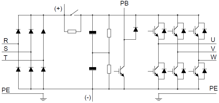
Figure 3-1 Main circuit of 380V VFDs (≤ 30kW)
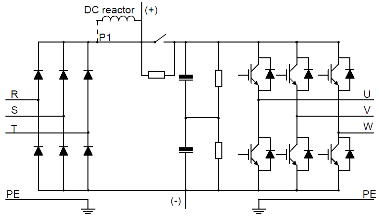
Figure 3-2 Main circuit of 380V VFDs (≥37kW)
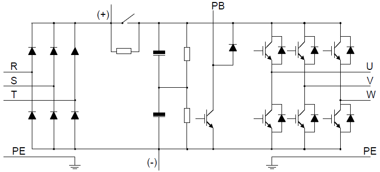
Figure 3-3 Main circuit of 500V VFDs (≤18.5kW)
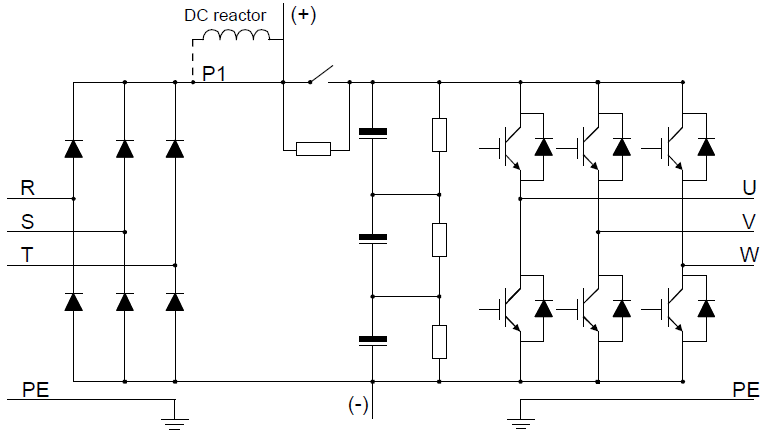
Figure 3-4 Main circuit of 500V VFDs (≥22kW)

Figure 3-5 Main circuit of 660V VFDs
Note:
1. The VFDs of 380V (≥37kW) supports external DC reactors and external braking units, but it is necessary to remove the copper tag between P1 and (+) before connecting. DC reactors and external braking units are optional.
2. The VFDs of 380V (≤30kW) supports external braking resistors which are optional.
3. The VFDs of 500V (≥22kW) supports external DC reactors and external braking units, but it is necessary to remove the copper tag between P1 and (+) before connecting. DC reactors and external braking units are optional.
4. The VFDs of 500V (≤18.5kW) supports external braking resistors which are optional.
5. The VFDs of 660V supports external DC reactors and external braking units, but it is necessary to remove the copper tag between P1 and (+) before connecting. DC reactors and external braking units are optional.