Please check according to the installation list in chapter two.
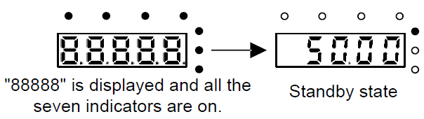
Check to ensure there is no mistake in wiring and power supply, switch on the air switch of the AC power supply on the input side of the VFD to power on the VFD. 8.8.8.8.8. will be displayed on the keypad, and the contactor closes normally. When the character on the nixie tubs changes to the set frequency, the VFD has finished the initialization and it is in the stand-by state.
Below diagram shows the first operation: (take motor 1 as the example)
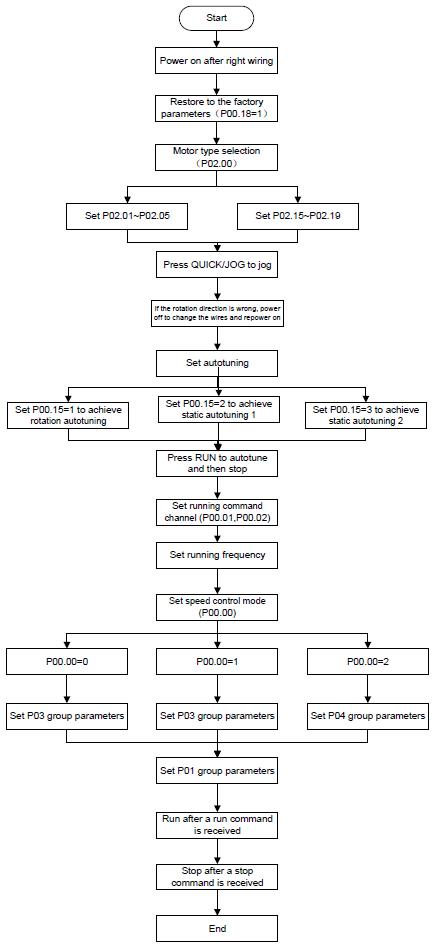
Note:If fault occurs, please do as the "Fault Tracking". Esitimate the fault reason and settle the issue.
Besides P00.01 and P00.02, terminal command setting can also used to set the running command channel.
Current running command channel P00.01 | Multi-function terminal 36 Switch to keypad | Multi-function terminal 37 Switch to to terminal | Multi- function terminal 38 Switch to commun- ication |
Keypad | / | Terminal | Communication |
Terminal | Keypad | / | Communication |
Communication | Keypad | Terminal | / |
Note: "/" means the multi-function terminal is invalid on the current given channel.
Related parameters:
Function code | Name | Detailed instruction of parameters | Default value |
P00.00 | Speed control mode | 0: Sensorless vector control mode 0 (apply to AM and SM) 1: Sensorless vector control mode 1 (applying to AM) 2: SVPWM control | 1 |
P00.01 | Running command channel | 0: Keypad 1:Terminal ("LOCAL/REMOT" flickering) 2:Communication ("LOCAL/REMOT" on) | 0 |
P00.02 | Communication running commands | 0: Modbus communication channel 1: PROFIBUS\CANopen communication channel 2: Ethernet communication channel 3: Reserved | 0 |
P00.18 | Function restore parameter | 0: No operation 1: Restore the default value 2: Cancel the fault record | 0 |
P00.15 | Motor parameter autotuning | 0: No operation 1: Rotating autotuning 2: Static autotuning 1 (autotune totally) 3: Static autotuning 2 (autotune part parameters) | 0 |
P02.00 | Motor type 1 | 0: Asynchronous motor 1: Synchronous motor | 0 |
P02.01 | Rated power of asynchronous motor 1 | 0.1–3000.0kW | Depend on model |
P02.02 | Rated frequency of asynchronous motor 1 | 0.01Hz–P00.03 (Max. output frequency) | 50.00Hz |
P02.03 | Rated speed of asynchronous motor 1 | 1–36000rpm | Depend on model |
P02.04 | Rated voltage of asynchronous motor 1 | 0–1200V | Depend on model |
P02.05 | Rated current of asynchronous motor 1 | 0.8–6000.0A | Depend on model |
P02.15 | Rated power of synchronous motor 1 | 0.1–3000.0kW | Depend on model |
P02.16 | Rated frequency of synchronous motor 1 | 0.01Hz–P00.03 (Max. frequency) | 50.00Hz |
P02.17 | Number of poles pairs for synchronous motor 1 | 1–50 | 2 |
P02.18 | Rated voltage of synchronous motor 1 | 0–1200V | Depend on model |
P02.19 | Rated current of synchronous motor 1 | 0.8–6000.0A | Depend on model |
P05.01–P05.09 | Multi-function digital input terminals (S1–S8,HDI) function selection | 36: Shift the command to keypad 37: Shift the command to terminals 38: Shift the command to communication | |
P07.01 | Parameter copy | The function code determines the manner of parameters copy. 0: No operation 1: Upload the local function parameter to the keypad 2: Download the keypad function parameter to local address (including the motor parameters) 3: Download the keypad function parameter to local address (excluding the motor parameter of P02 and P12 group) 4: Download the keypad function parameters to local address (only for the motor parameter of P02 and P12 group) | 0 |
P07.02 | QUICK/JOG function selection | 0: No function 1: Jogging 2: Shift the display state by the shifting key 3: Shift between forward rotations and reverse rotations 4: Clear UP/DOWN settings 5: Coast to stop 6: Shift the given manner of running commands 7: Quick commission mode (committee according to the non-factory parameter) | 1 |