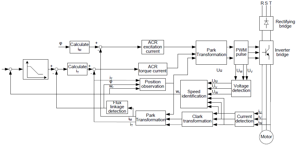
Because asynchronous motors have the characteristics of high stage, nonlinear, strong coupling and various variables, the actual control of the asynchronous motor is very difficult. Vector control is mainly used to settle this problem with the theme of that divide the stator current vector into exciting current (the current heft generating internal magnetic field of the motor) and torque current (the current heft generating torque) by controlling and measuring the stator current vector according to the principles of beamed magnetic field to control the range and phase of these two hefts. This method can realize the decoupling of exciting current and torque current to adjust the high performance of asynchronous motors.
Goodrive300 series VFDs are embedded speedless sensor vector control calculation for driving both asynchronous motors and synchronous motors. Because the core calculation of vector control is based on exact motor parameter models, the accuracy of motor parameter will impact on the performance of vector control. It is recommended to input the motor parameters and carry out autotune before vector running.
Because the vector control calculation is vary complicated, high technical theory is needed for the user during internal autotune. It is recommended to use the specific function parameters in vector control with cautions.
Function code | Name | Detailed instruction of parameters | Default value |
P00.00 | Speed control mode | 0: Sensorless vector control mode 0 (apply to AM and SM) 1: Sensorless vector control mode 1 (applying to AM) 2: SVPWM control | 1 |
P00.15 | Motor parameter autotuning | 0: No operation 1: Rotating autotuning 2: Static autotuning 1 (autotune all motor parameters) 3: Static autotuning 2 (autotune some of the motor parameters) | 0 |
P02.00 | Type of motor 1 | 0: Asynchronous motor 1: Synchronous motor | 0 |
P03.00 | Speed loop proportional gain1 | 0–200.0 | 20.0 |
P03.01 | Speed loop integral time1 | 0.000–10.000s | 0.200s |
P03.02 | Low switching frequency | 0.00Hz–P03.05 | 5.00Hz |
P03.03 | Speed loop proportional gain 2 | 0–200.0 | 20.0 |
P03.04 | Speed loop integral time 2 | 0.000–10.000s | 0.200s |
P03.05 | High switching frequency | P03.02–P00.03 (Max. frequency) | 10.00Hz |
P03.06 | Speed loop output filter | 0–8 (corresponding to 0–28/10ms) | 0 |
P03.07 | Compensation coefficient of electromotion slip in vector control | 50%–200% | 100% |
P03.08 | Compensation coefficient of braking slip in vector control | 50%–200% | 100% |
P03.09 | Current loop proportional coefficient P | 0–65535 | 1000 |
P03.10 | Current loop integral coefficient I | 0–65535 | 1000 |
P03.11 | Torque setting method | This parameter is used to enable the torque control mode, and set the torque. 0: Torque control is invalid 1: Keypad setting torque (P03.12) 2: Analog AI1 setting torque 3: Analog AI2 setting torque 4: Analog AI3 setting torque 5: Pulse frequency HDI setting torque 6: Multi-step torque setting 7: Modbus communication setting torque 8: PROFIBUS/CANopen communication setting torque 9: Ethernet communication setting torque 10: Reserved Note: For setting modes of 2–10, 100% corresponds to three times of the rated current of the motor. | 0 |
P03.12 | Keypad setting torque | -300.0%–300.0% (rated current of the motor) | 50.0% |
P03.13 | Torque reference filter time | 0.000–10.000s | 0.010s |
P03.14 | Upper frequency of forward rotation in torque control | 0: Keypad (P03.16 sets P03.14, P03.17 sets P03.15) 1: AI1 2: AI2 3: AI3 4: Pulse frequency HDI 5: Multi-step 6: Modbus communication 7: PROFIBUS/CANopen communication 8: Ethernet communication 9: Reserved Note: For setting modes of 1–9, 100% corresponds to the maximum frequency. | 0 |
P03.15 | Upper frequency of reverse rotation in torque control | 0 | |
P03.16 | Keypad setting for upper frequency of forward rotation in torque control | Setting range: 0.00Hz–P00.03 (Max. output frequency) | 50.00Hz |
P03.17 | Keypad setting for upper frequency of reverse rotation in torque control | 50.00Hz | |
P03.18 | Upper electromotion torque limit setting source | 0: Keypad (P03.20 sets P03.18, P03.21 sets P03.19) 1: AI1 2: AI2 3: AI3 4: HDI 5: Modbus communication 6: PROFIBUS/CANopen communication 7: Ethernet communication 8: Reserved | 0 |
P03.19 | Upper braking torque limit setting source | 0 | |
P03.20 | Keypad setting of electromotion torque | 0.0–300.0% (rated current of the motor) | 180.0% |
P03.21 | Keypad setting of braking torque | 180.0% | |
P03.22 | Weakening coefficient in constant power zone | 0.1–2.0 | 0.3 |
P03.23 | Lowest weakening point in constant power zone | 10%–100% | 20% |
P03.24 | Max. voltage limit | 0.0–120.0% | 100.0% |
P03.25 | Pre-exciting time | 0.000–10.000s | 0.300s |
P17.32 | Magnetic flux linkage | 0.0–200.0% | 0 |