Goodrive300 series VFDs have 2 relay output terminals, 1 open collector output terminal Y, and 1 high-speed pulse output terminal (HDO) in the standard configuration. All functions of the digital output terminals are programmable by using function codes, where the HDO can be set to high-speed pulse output or switch output through function codes.
The following table is the option of the four function parameters and selecting the repeated output terminal function is allowed.
Set value | Function | Instructions |
0 | Invalid | The output terminal has no function. |
1 | Running | Output ON signal when the VFD is running and there is frequency output. |
2 | Forward running | Output ON signal when the VFD is running forward and there is frequency output. |
3 | Reverse running | Output ON signal when the VFD is running reverse and there is frequency output. |
4 | Jogging | Output ON signal when the VFD is jogging and there is frequency output. |
5 | VFD fault | Output ON signal when the VFD is in fault |
6 | FDT1 | Please refer to P08.32 and P08.33 for detailed information. |
7 | FDT2 | Please refer to P08.34 and P08.35 for detailed information. |
8 | Frequency arrival | Please refer to P08.36 for detailed information. |
9 | Zero-speed running | Output ON signal when the output frequency and given frequency of the VFD is 0 at the same time. |
10 | Upper-limit frequency arrival | Output ON signal when the running frequency of the VFD is the upper limit frequency. |
11 | Upper-limit frequency arrival | Output ON signal when the running frequency of the VFD is the lower limit frequency. |
12 | Ready | When the main circuit and the control circuit is established and the protection function of the VFD is not active. The VFD is in the running state and it will output ON signal. |
13 | Pre-exciting | Output ON signal when the VFD is in the pre-exciting state. |
14 | Overload pre-alarm | Output ON signal if the VFD is beyond the pre-alarm point. Refer to P11.08–P11.10 for the detailed instruction. |
15 | Underload pre-alarm | Output ON signal if the VFD is beyond the pre-alarm point. Refer to P11.11–P11.12 for the detailed instruction. |
16 | Simple PLC stage completion | Output signal if the simple PLC stage is completed. |
17 | Simple PLC cycle completion | Output signal if the simple PLC cycle is completed. |
18 | Set counting arrival | Output ON signal if the detected counting exceeds the set value of P08.25. |
19 | Fixed counting arrival | Output ON signal if the detected counting exceeds the set value of P08.26. |
20 | External fault valid | Output ON signal if external fault occurs. |
21 | Length arrival | Output ON signal if the actual detected length exceeds the set length by P08.19. |
22 | Running time arrival | Output ON signal if the accumulative running time of the VFD exceeds the setting time by P08.27. |
23 | Modbus communication virtual terminal output | Output corresponding signal according to the setting value of Modbus. Output ON signal if the setting value is 1 and output OFF signal if the setting value is 0. |
24 | POROFIBUS communication virtual terminal output | Output a corresponding signal according to the set value of PROFIBUS/CANOPEN. Output the signal of ON if the set value is 1 and output the signal of OFF if the set value is 0. |
25 | Ethernet communication Virtual terminal output | Output a corresponding signal according to the set value of Ethernet. Output the signal of ON if the set value is 1 and output the signal of OFF if the set value is 0. |
26 | DC bus voltage establishment finished | The output is vlaid when the bus voltage reaches the undervoltage point of the inverter. |
27–30 | Reserved |
Related parameters
Function code | Name | Detailed instruction of parameters | Default value |
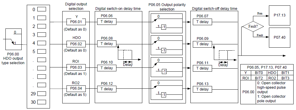
P06.00 | HDO output | 0: Open collector high-speed pulse output 1: Open collector output | 0 |
P06.01 | Y output | 0: Invalid 1: In operation 2: Forward rotation operation 3: Reverse rotation operation 4: Jogging operation 5: The VFD fault 6: Frequency degree test FDT1 7: Frequency degree test FDT2 8: Frequency arrival 9: Zero speed running 10: Upper limit frequency arrival 11: Lower limit frequency arrival 12: Ready for operation 13: Pre-magnetizing 14: Overload pre-alarm 15: Underload pre-alarm 16: Completion of simple PLC stage 17: Completion of simple PLC cycle 18: Set count value reached 19: Specified count value reached 20: External fault valid 21: Length arrival 22: Running time arrival 23: Modbus communication virtual terminals output 24: PROFIBUS/CANopen communication virtual terminals output 25: Ethernet communication virtual terminals output 26: Voltage establishment finished 27–30: Reserved | 0 |
P06.02 | HDO output | 0 | |
P06.03 | Relay RO1 output | 1 | |
P06.04 | Relay RO2 output | 5 | |
P06.05 | Polarity of output terminals | 0x00–0x0F | 0x00 |
P06.06 | Y switch-on delay time | 0.000–50.000s | 0.000s |
P06.07 | Y switch-off delay time | 0.000–50.000s | 0.000s |
P06.08 | HDO switch-on delay time | 0.000–50.000s (valid only when P06.00=1) | 0.000s |
P06.09 | HDO switch-off delay time | 0.000–50.000s (valid only when P06.00=1) | 0.000s |
P06.10 | RO1 switch-on delay time | 0.000–50.000s | 0.000s |
P06.11 | RO1 switch-off delay time | 0.000–50.000s | 0.000s |
P06.12 | RO2 switch-on delay time | 0.000–50.000s | 0.000s |
P06.13 | RO2 switch-off delay time | 0.000–50.000s | 0.000s |
P07.40 | Output terminals state at current fault | 0 | |
P17.13 | Digital output terminals state | 0 |