P17.00 | Setting frequency | Display current set frequency of the VFD. Range: 0.00Hz–P00.03 | 0.00Hz | ● |
P17.01 | Output frequency | Display current output frequency of the VFD. Range: 0.00Hz–P00.03 | 0.00Hz | ● |
P17.02 | Ramp reference frequency | Display current ramp given frequency of the VFD. Range: 0.00Hz–P00.03 | 0.00Hz | ● |
P17.03 | Output voltage | Display current output voltage of the VFD. Range: 0–1200V | 0V | ● |
P17.04 | Output current | Display current output current of the VFD. Range: 0.0–3000.0A | 0.0A | ● |
P17.05 | Motor speed | Display the rotation speed of the motor. Range: 0–65535RPM | 0 RPM | ● |
P17.06 | Torque current | Display current torque current of the VFD. Range: -3000.0–3000.0A | 0.0A | ● |
P17.07 | Exciting current | Display current exciting current of the VFD. Range: -3000.0–3000.0A | 0.0A | ● |
P17.08 | Motor power | Display current power of the motor. Setting range: -300.0%–300.0% (the rated current of the motor) | 0.0% | ● |
P17.09 | Output torque | Display the current output torque of the VFD. Range: -250.0–250.0% | 0.0% | ● |
P17.10 | Evaluated motor frequency | Evaluate the motor rotor frequency on close loop vector. Range: 0.00– P00.03 | 0.00Hz | ● |
P17.11 | DC bus voltage | Display current DC bus voltage of the VFD. Range: 0.0–2000.0V | 0.0V | ● |
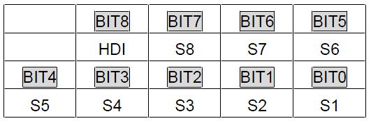
P17.12 | Digital input terminals state | Display current Switch input terminals state of the VFD.
Range: 0000–01FF | 0 | ● |
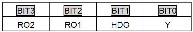
P17.13 | Digital output terminals state | Display current Switch output terminals state of the VFD.
Range: 0000–000F | 0 | ● |
P17.14 | Digital adjustment | Display the adjustment through the keypad of the VFD. Range: 0.00Hz–P00.03 | 0.00Hz | ● |
P17.15 | Torque reference | Display the torque given, the percentage to the current rated torque of the motor. Setting range: -300.0%–300.0% (the rated current of the motor) | 0.0% | ● |
P17.16 | Linear speed | Display the current linear speed of the VFD. Range: 0–65535 | 0 | ● |
P17.17 | Length | Display the current length of the VFD. Range: 0–65535 | 0 | ● |
P17.18 | Count value | Display the current counting number of the VFD. Range: 0–65535 | 0 | ● |
P17.19 | AI1 input voltage | Display analog AI1 input signal. Range: 0.00–10.00V | 0.00V | ● |
P17.20 | AI2 input voltage | Display analog AI2 input signal. Range: 0.00–10.00V | 0.00V | ● |
P17.21 | AI3 input voltage | Display analog AI2 input signal. Range: -10.00–10.00V | 0.00V | ● |
P17.22 | HDI input frequency | Display HDI input frequency. Range: 0.000–50.000kHz | 0.000 kHz | ● |
P17.23 | PID reference | Display PID given value. Range: -100.0–100.0% | 0.0% | ● |
P17.24 | PID feedback | Display PID response value. Range: -100.0–100.0% | 0.0% | ● |
P17.25 | Power factor of the motor | Display the current power factor of the motor. Range: -1.00–1.00 | 0.0 | ● |
P17.26 | Current running time | Display the current running time of the VFD. Range:0–65535m | 0m | ● |
P17.27 | Simple PLC and the current step of the multi-step speed | Display simple PLC and the current stage of the multi-step speed. Range: 0–15 | 0 | ● |
P17.28 | ASR controller output | The percentage of the rated torque of the corresponding motor, display ASR controller output. Range: -300.0%–300.0% (the rated current of the motor) | 0.0% | ● |
P17.29 | Magnetic pole angle of SM | Display synchronous motor Magnetic pole angle. Range: 0.0–360.0 | 0.0 | ● |
P17.30 | Phase compensation of SM | Display synchronous motor phase compensation. Range: -180.0–180.0 | 0.0 | ● |
P17.31 | High-frequency superimposed current of SM | Display synchronous motor high-frequency Superimposed current. Range: 0.0%–200.0% (the rated current of the motor) | 0.0 | ● |
P17.32 | Magnetic flux linkage | Display the magnetic flux linkage of the motor. Range: 0.0%–200.0% | 0.0% | ● |
P17.33 | Exciting current reference | Display the exciting current reference in the vector control mode. Range: -3000.0–3000.0A | 0.0A | ● |
P17.34 | Torque current reference | Display the torque current reference in the vector control mode. Range: -3000.0–3000.0A | 0.0A | ● |
P17.35 | AC current | Display the value of inlet current in AC side. Range: 0.0–5000.0A | 0.0A | ● |
P17.36 | Output torque | Display the output torque. Positive value is in the electromotion state, and negative is in the power generating state. Range : -3000.0Nm–3000.0Nm | 0.0Nm | ● |
P17.37 | Count value of motor overload | 0–100 (100 reports OL1 fault) | 0 | ● |
P17.38 | PID output | -100.00–100.00% | 0.00% | ● |
P17.39 | Wrong download of parameters | 0.00–99.99 | 0.00 | ● |