Below is the layout figure of the VFD (take the VFD of 460V G-type 30kW as the example).
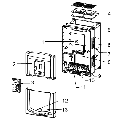
Figure 3-6 Product structure
Serial No. | Name | Illustration |
1 | Keypad port | Connect the keypad |
2 | Upper cover | Protect the internal parts and components |
3 | Keypad | See Keypad operation procedure for detailed information |
4 | Cooling fan | See Maintenance and hardware diagnostics for detailed information |
5 | Wiring port | Connect to the control board and the drive board |
6 | Name plate | See Product Overview for detailed information |
7 | Side cover | Optional. The side cover will increase the protective degree of the VFD. The internal temperature of the VFD will increase, too, so it is necessary to derate the VFD at the same time |
8 | Control terminals | See Installation guidelines for detailed information |
9 | Main circuit terminals | See Installation guidelines for detailed information |
10 | Main circuit cable port | Fix the main circuit cable |
11 | POWER light | Power indicator |
12 | Simple name plate | See Type designation key for detailed information |
13 | Lower cover | Protect the internal parts and components |