4.2.1 Installation environment
The installation environment is the safeguard for a full performance and long-term stable functions of the VFD. Check the installation environment as follows:
Environment | Conditions |
Installation site | Indoor |
Environment temperature | -10–+50°C If the ambient temperature of the VFD is above 40°C, derate according to the detailed information of Appendix B. It is not recommended to use the VFD if ambient temperature is above 50°C. In order to improve the reliability of the device, do not use the VFD if the ambient temperature changes frequently. Please provide cooling fan or air conditioner to control the internal ambient temperature below the required one if the VFD is used in a closed space such as in the control cabinet. When the temperature is too low, if the VFD needs to restart to run after a long stop, it is necessary to provide an external heating device to increase the internal temperature, otherwise damage to the devices may occur. |
Humidity | RH≤90% No condensation is allowed. The max relative humidity should be equal to or less than 60% in corrosive air. |
Storage temperature | -30–+60°C |
Running environment condition | The installation site of the VFD should:
|
Altitude | <1000m When the installation site altitude exceeds 1000m, derate 1% for every increase of 100m; when the installation site altitude exceeds 3000m, consult the local INVT dealer or office. |
Vibration | ≤ 5.88m/s2(0.6g) |
Installation direction | The VFD should be installed on an upright position to ensure sufficient cooling effect. |
Note:
Goodrive310-UL series VFDs should be installed in a clean and ventilated environment according to enclosure classification.
Cooling air must be clean, free from corrosive materials and electrically conductive dust.
4.2.2 Installation direction
The VFD may be installed in a cabinet.
The VFD must be installed in an upright position. Check the installation site according to the requirements below. Refer to chapter Dimension drawings in the appendix for frame details.
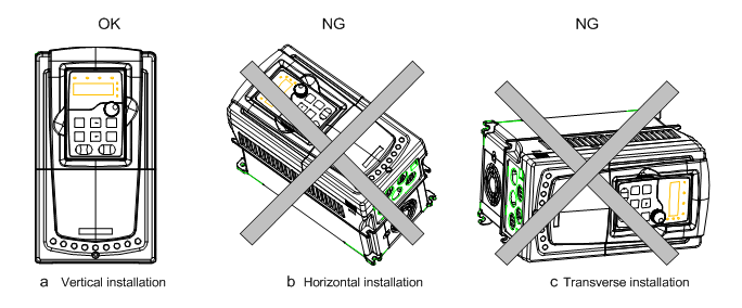
Figure 4-1 Installation direction of the VFD
4.2.3 Installation manner
The VFD can be installed in three different ways, depending on the frame size:
a) Wall mounting (for the VFDs of 220V ≤55kW; 460V G-type≤200kW, P-type≤220kW and 575V)
b) Flange mounting (for the VFDs of 220V ≤55kW; 460V G-type≤200kW, P-type≤220kW and 575V)
c) Floor mounting (for the VFDs of 460V G-type 220–500kW, P-type 250–500kW)
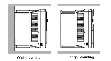
Figure 4-2 Installation manner
(1) Mark the hole location. The location of the holes is shown in the dimension drawings in the Appendix C.
(2) Fix the screws or bolts to the marked locations.
(3) Put the VFD against the wall.
(4)Tighten the screws in the wall securely.
Note:
The flange installation of the VFDs of 220V 0.75–15kW and 460V G-type 1.5–30kW, P-type 5.5–37kW need flange board, while the flange installation of the VFDs of 220V 18.5–55kW and 460V G-type 37–200kW, P-type 45–220kW does not need.
4.2.4 Single installation
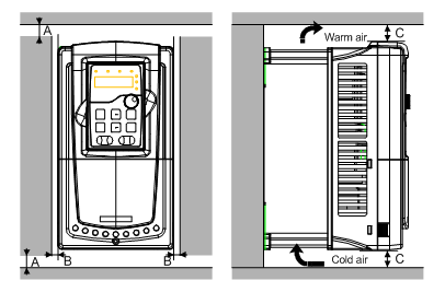
Figure 4-3 Single installation
Note: The minimum space of B and C is 100mm.
4.2.5 Multiple installations
Parallel installation
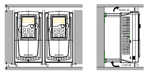
Figure 4-4 Parallel installation
Note:
Before installing the different sizes VFDs, please align their top position for the convenience of later maintenance.
The minimum space of B, D and C is 100mm.
4.2.6 Vertical installation
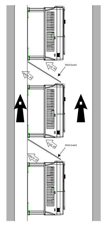
Figure 4-5 Vertical installation
Note: Windscreen should be installed in vertical installation for avoiding mutual impact and insufficient cooling.
4.2.7 Slanting installation
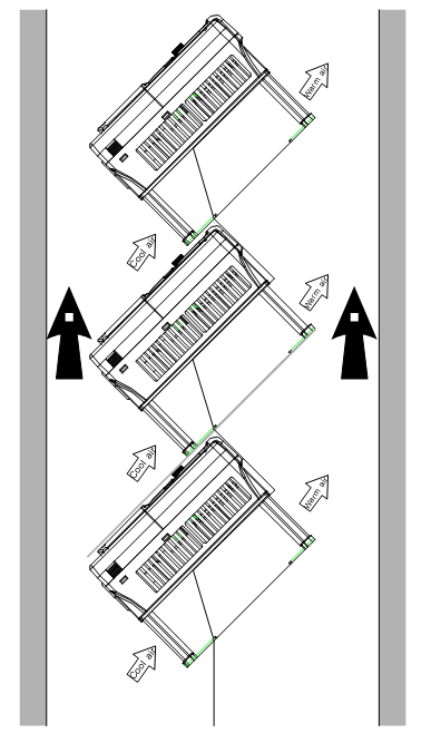
Figure 4-6 Slanting installation
Note: Ensure the separation of the wind input and output channels in slanting installation for avoiding mutual impact.