|
|
|
|


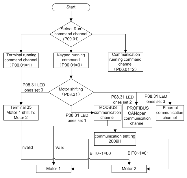
Goodrive310-UL series VFDs can drive both asynchronous motors and synchronous motors. And at the same time, they can support two sets of motor parameters which can shift between two motors through multi-function digital input terminal or communication.
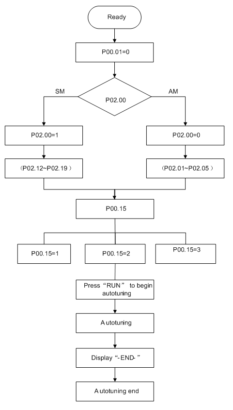
The control performance of the VFD is based on the established accurate motor model. The user has to carry out the motor autotune before first running (take motor 1 as the example).
Note:
1. Set the motor parameters according to the name plate of the motor.
2. During the motor autotune, de-couple the motor from the load if rotation autotune is selected to make the motor is in a static and empty state, otherwise the result of autotune is incorrect. The asynchronous motors can autotune the parameters of P02.06–P02.10, while the synchronous motors can autotune the parameters of P02.20–P02.23.
3. During the motor autotune, do not to de-couple the motor from the load if static autotune is selected. Because only some parameters of the motor are involved, the control performance is not as better as the rotation autotune. The asynchronous motors can autotune the parameters of P02.06–P02.10, while the synchronous motors can autotune the parameters of P02.20–P02.22. P02.23 (synchronous motor 1 counter-electromotive force constant) can be counted to attain.
4. Motor autotune only involves the current motor. Switch the motor through P08.31 to carry out the autotune on the other motor.
Related parameters list:
Function code | Name | Detailed instruction of parameters | Default value |
P00.01 | Run command channel | 0: Keypad running command 1: Terminal running command channel (“LOCAL/REMOT” flickering) 2: Communication running command channel (“LOCAL/REMOT” on); | 0 |
P00.15 | Motor parameter autotuning | 0: No operation 1: Rotating autotuning 2: Static autotuning 1 (autotune totally) 3: Static autotuning 2 (autotune part parameters) | 0 |
P02.00 | Motor type 1 | 0: Asynchronous motor 1: Synchronous motor | 0 |
P02.01 | Rated power of AM 1 | 0.1–3000.0kW | Depend on model |
P02.02 | Rated frequency of AM 1 | 0.01Hz–P00.03 (the max frequency) | 60.00Hz |
P02.03 | Rated speed of AM 1 | 1–36000rpm | Depend on model |
P02.04 | Rated voltage of AM 1 | 0–1200V | Depend on model |
P02.05 | Rated current of AM 1 | 0.8–6000.0A | Depend on model |
P02.06 | Stator resistor of AM 1 | 0.001–65.535Ω | Depend on model |
P02.07 | Rotor resistor of AM 1 | 0.001–65.535Ω | Depend on model |
P02.08 | Leakage inductance of AM 1 | 0.1–6553.5mH | Depend on model |
P02.09 | Mutual inductance of AM 1 | 0.1–6553.5mH | Depend on model |
P02.10 | Non-load current of AM1 | 0.1–6553.5A | Depend on model |
P02.15 | Rated power of SM 1 | 0.1–3000.0kW | Depend on model |
P02.16 | Rated frequency of SM 1 | 0.01Hz–P00.03 (the max frequency) | 60.00Hz |
P02.17 | Number of poles pairs for SM 1 | 1–50 | 2 |
P02.18 | Rated voltage of SM 1 | 0–1200V | Depend on model |
P02.19 | Rated current of SM 1 | 0.8–6000.0A | Depend on model |
P02.20 | Stator resistor of SM 1 | 0.001–65.535Ω | Depend on model |
P02.21 | Direct axis inductance of SM 1 | 0.01–655.35mH | Depend on model |
P02.22 | Quadrature axis inductance of SM 1 | 0.01–655.35mH | Depend on model |
P02.23 | Back EMF constant of SM 1 | 0–10000 | 300 |
P05.01–P05.09 | Multi-function digital input terminals (S1–S8, HDI) function selection | 35: Shift from motor 1 to motor 2 | |
P08.31 | Motor shifting | LED ones: shifting channel 0: terminal shifting 1: MODBUS communication shifting 2: PROFIBUS/CANopen communication shifting 3: Ethernet communication shifting 4: Reserved LED tens: shifting enabling in operation 0: Disabled 1: Enabled 0x00–0x14 | 00 |
P12.00 | Motor type 2 | 0: Asynchronous motor 1: Synchronous motor | 0 |
P12.01 | Rated power of AM 2 | 0.1–3000.0kW | Depend on model |
P12.02 | Rated frequency of AM 2 | 0.01Hz–P00.03 (the max frequency) | 60.00Hz |
P12.03 | Rated speed of AM 2 | 1–36000rpm | Depend on model |
P12.04 | Rated voltage of AM 2 | 0–1200V | Depend on model |
P12.05 | Rated current of AM 2 | 0.8–6000.0A | Depend on model |
P12.06 | Stator resistor of AM 2 | 0.001–65.535Ω | Depend on model |
P12.07 | Rotor resistor of AM 2 | 0.001–65.535Ω | Depend on model |
P12.08 | Leakage inductance of AM 2 | 0.1–6553.5mH | Depend on model |
P12.09 | Mutual inductance of AM 2 | 0.1–6553.5mH | Depend on model |
P12.10 | Non-load current of AM 2 | 0.1–6553.5A | Depend on model |
P12.15 | Rated power of SM 2 | 0.1–3000.0kW | Depend on model |
P12.16 | Rated frequency of SM 2 | 0.01Hz–P00.03 (the max frequency) | 60.00Hz |
P12.17 | Number of poles pairs for SM 2 | 1–50 | 2 |
P12.18 | Rated voltage of SM 2 | 0–1200V | Depend on model |
P12.19 | Rated current of SM 2 | 0.8–6000.0A | Depend on model |
P12.20 | Stator resistor of SM 2 | 0.001–65.535Ω | Depend on model |
P12.21 | Direct axis inductance of SM 2 | 0.01–655.35mH | Depend on model |
P12.22 | Quadrature axis inductance of SM 2 | 0.01–655.35mH | Depend on model |
P12.23 | Back EMF constant of SM 2 | 0–10000 | 300 |