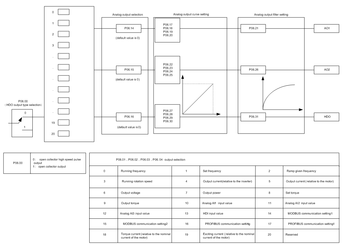
Goodrive310-UL series VFDs have 2 analog output terminals (0–10V or 0–20mA) and 1 high speed pulse output terminal. Analog output signal can be filtered and the maximum and minimum values can be adjusted. The analog output signals can be proportional to motor speed, output frequency, output current, motor torque, motor power, etc.
Output instructions:
Function | Instructions | |
0 | Running frequency | 0–the max output frequency |
1 | Set frequency | 0– the max output frequency |
2 | Ramp given frequency | 0– the max output frequency |
3 | Running speed | 0–2 times of the rated synchronous rotation speed of the motor |
4 | Output current (relative to the VFD) | 0–2 times of the rated current of the VFD |
5 | Output current (relative to the motor) | 0–2 times of the rated current of the VFD |
6 | Output voltage | 0–1.5 times of the rated voltage of the VFD |
7 | Output power | 0–2 times of the rated power |
8 | Setting torque value | 0–2 times of the rated current of the motor |
9 | Output torque | 0–2 times of the rated current of the motor |
10 | AI1 | 0–10V/0–20mA |
11 | AI2 | 0–10V/0–20mA |
12 | AI3 | -10V–10V |
13 | HDI | 0.00–50.00kHz |
14 | Setting value 1 of MODBUS communication | -1000–1000, 1000 corresponds to 100.0% |
15 | Setting value 2 of MODBUS communication | -1000–1000, 1000 corresponds to 100.0% |
16 | Setting value 1 of PROFIBUS/CANOPEN communication | -1000–1000, 1000 corresponds to 100.0% |
17 | Setting value 2 of PROFIBUS/CANOPEN communication | -1000–1000, 100 corresponds to 100.0% |
18 | Setting value 1 of Ethernet communication | -1000–1000, 1000 corresponds to 100.0% |
19 | Setting value 2 of Ethernet communication | -1000–1000, 100 corresponds to 100.0% |
20–21 | Reserved | |
22 | Torque current (relative to the rated current of the motor) | 0–2 times of the rated current of the motor |
23 | Exciting current (relative to the rated current of the motor) | 0–2 times of the rated current of the motor |
24–30 | Reserved |
Related parameters list:
Function code | Name | Detailed instruction of parameters | Default value | |
P06.00 | HDO output | 0: Open collector pole high speed pulse output 1: Open collector pole output. | 0 | |
P06.14 | AO1 output | 0: Running frequency 1: Set frequency 2: Ramp reference frequency 3: Running rotation speed 4: Output current (relative to the rated current of the VFD) 5: Output current (relative to the rated current of the motor) 6: Output voltage 7: Output power 8: Set torque value 9: Output torque 10: AI1 input value 11: AI2 input value 12: AI3 input value 13: High speed pulse HDI input value 14: MODBUS communication set value 1 15: MODBUS communication set value 2 16: PROFIBUS/CANopen communication set value 1 17: PROFIBUS/CANopen communication set value 2 18: Ethernet communication set value 1 19: Ethernet communication set value 2 20–21: Reserved 22: Torque current (relative to the rated current of the motor) 23: Pre-magnetizing current (relative to the rated current of the motor) 24–30: Reserved | 0 | |
P06.15 | AO2 output | 0 | ||
P06.16 | HDO high-speed pulse output | 0 | ||
P06.17 | Lower output limit of AO1 | -100.0%–P06.19 | 0.0% | |
P06.18 | Corresponding AO1 output of lower limit | 0.00V–10.00V | 0.00V | |
P06.19 | Upper output limit of AO1 | P06.17–100.0% | 100.0% | |
P06.20 | The corresponding AO1 output of upper limit | 0.00V–10.00V | 10.00V | |
P06.21 | AO1 output filter time | 0.000s–10.000s | 0.000s | |
P06.22 | Lower output limit of AO2 | -100.0%–P06.24 | 0.0% | |
P06.23 | Corresponding AO2 output of lower limit | 0.00V–10.00V | 0.00V | |
P06.24 | Upper output limit of AO2 | P06.22–100.0% | 100.0% | |
P06.25 | The corresponding AO2 output of upper limit | 0.00V–10.00V | 10.00V | |
P06.26 | AO2 output filter time | 0.000s–10.000s | 0.000s | |
P06.27 | Lower output limit of HDO | -100.0%–P06.29 | 0.00% | |
P06.28 | Corresponding HDO output of lower limit | 0.00–50.00kHz | 0.0kHz | |
P06.29 | Upper output limit of HDO | P06.27–100.0% | 100.0% | |
P06.30 | Corresponding HDO output of upper limit | 0.00–50.00kHz | 50.00kHz | |
P06.31 | HDO output filter time | 0.000s–10.000s | 0.000s | |