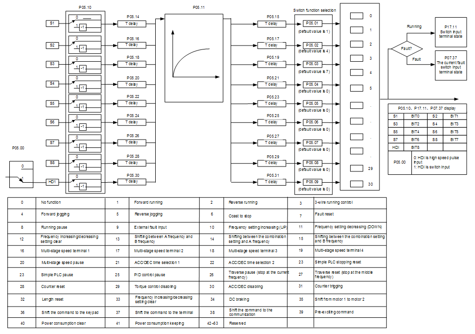
Goodrive310-UL series VFDs have 8 programmable digital input terminals and 1 open circuit electrode output terminal in the standard configuration. All functions of the digital input terminals are programmable by the function codes. Open collector pole input can be selected into high speed pulse input terminal or common switch input terminal by function code. When selected into HDI, the user can select HDI high speed pulse input as frequency given, counting input or length pulse input by setting.
This parameter is used to set the function corresponds to the digital multi-function terminals.
Note: two different multi-function terminals cannot be set as one function.
Set value | Function | Instructions |
0 | No function | The VFD does not work even there is input signal. It is necessary to set the terminal which cannot be used to non-function to avoid misacting. |
1 | Forward running (FWD) | The forward or reverse rotation of the VFD can be controlled by the external terminals. |
2 | Reverse running (REV) | |
3 | 3-wire running control | The terminal can determine the running mode of the VFD is 3-wire control mode. Refer to P05.13 for detailed instruction of 3-wire control mode. |
4 | Forward jogging | See P08.06, P08.07 and P08.08 for jogging frequency, jogging ACC/DEC time. |
5 | Reverse jogging | |
6 | Coast to stop | The VFD closes off the output. The motor is not controlled by the VFD during the stopping. This method is usually to be used when the load inertia is big and it has no requirement to the stopping time. It has the same meaning with the “coast to stop” in P01.08 and usually used in remote control. |
7 | Fault reset | External fault reset. It has the same function with the reset function of STOP/RST on the keypad. This function can realize remote fault reset. |
8 | Operation pause | The VFD decelerates to stop. But all running parameters are in the memory state. For example, PLC parameters, traverse parameters and PID parameters. After the signal disappears, the VFD will come back to the state before stopping. |
9 | External fault input | When the external fault signal is sent to the VFD, the VFD will report the fault and stop. |
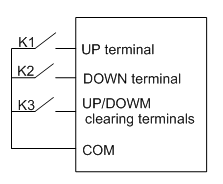
10 | Frequency setting up (UP) | This parameter is used to modify the increasing and decreasing command during the external terminal given frequency.
Frequency increasing/decreasing setting clear terminal can cancel the assistant channel frequency set by the internal UP/DOWN of the VFD to make the given frequency restore to the frequency given by the main given frequency channel. |
12 | Frequency setting down (DOWN) | |
12 | Frequency increasing/decreasing setting clear | |
13 | Switch between A setting and B setting | This function can realize the shifting between the frequency setting channels. The 13th function can ealize the shifting between A frequency given channel and B frequency given channel. The 14th function can realize the shifting between A frequency given channel and the combination setting channel set by P00.09 The 15th function can realize the shifting between B frequency given channel and the combination setting channel set by P00.09 |
14 | Switch between A setting and combination setting | |
15 | Switch between B setting and combination setting | |
16 | Multi-step speed terminal 1 | The 16 stage speeds can be set by the combination of digital state of four terminals. Note: multi-step speed 1 is the low bit, multi-step speed 4 is the high bit. 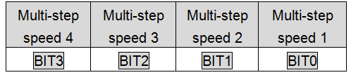 |
17 | Multi-step speed terminal 2 | |
18 | Multi-step speed terminal 3 | |
19 | Multi-step speed terminal 4 | |
20 | Multi-step speed pause | Shield the multi-step speed selection terminal function to keep the setting value at the current state. |
21 | ACC/DEC time selection 1 | Select 4 ACC/DEC time by the combination of the 2 terminals. 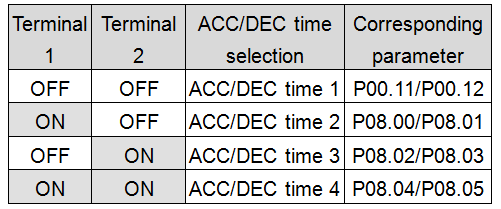 |
22 | ACC/DEC time selection 2 | |
23 | Simple PLC stop reset | Restart simple PLC and clear the memory state of PLC. |
24 | Simple PLC pause | Program pause during PLC implement. Run at the current speed stage. After cancel the function, simple PLC continues to run. |
25 | PID control pause | Temporal PID invalid and the VFD will output at the current frequency. |
26 | Traverse pause (stop at the current frequency) | The VFD will stop at the current output and after canceling the function, the VFD will continue to traverse run at the current frequency. |
27 | Traverse reset (return to the middle frequency) | The setting frequency of the VFD will come back to the middle frequency. |
28 | Counter reset | Counter clear |
29 | Torque control disabling | The VFD shifts from torque control mode to speed control mode. |
30 | ACC/DEC disabling | Ensure the VFD will not be affected by the external signals (except for the stopping command) and keep the current output frequency. |
31 | Counter trigging | Enable the pulse counter. |
32 | Length reset | Length counter clear |
33 | Frequency increasing/decreasing setting temporal clear | When the terminal closes, the frequency set by UP/DOWN can be cleared. All set frequency will be restored into the given frequency by the frequency command channel and the frequency will come back to the value after the frequency increasing or decreasing. |
34 | DC braking | The VFD will begin DC braking after the valid command. |
35 | Switch between motor1 and motor2 | Motor-shifting can be controlled after the terminal is valid. |
36 | Switch commands to keypad | After the function terminal become valid, the running command channel will be shifted into keypad running command channel and the running command channel will come back to the original state if function terminal is invalid. |
37 | Switch commands to terminals | After the function terminal become valid, the running command channel will be shifted into terminal running command channel and the running command channel will come back to the original state if function terminal is invalid. |
38 | Switch commands to communication | After the function terminal become valid, the running command channel will be shifted into communication running command channel and the running command channel will come back to the original state if function terminal is invalid. |
39 | Pre-excitation commands | Perform pre-exciting if the terminal is valid until the terminal is invalid. |
40 | Power consumption clear | The power consumption will be cleared after the command is valid. |
41 | Power consumption retention | If the command is valid, the current running of the VFD will not affect its power consumption. |
42–60 | Reserved | |
61 | PID pole switching | Switch the output pole of PID and be used with P09.03 |
62–63 | Reserved |
Related parameters list:
Function code | Name | Detailed instruction of parameters | Default value |
P05.00 | HDI input selection | 0: High pulse input 1: Digital input | 0 |
P05.01 | S1 terminals function selection | 0: No function 1: Forward rotation operation 2: Reverse rotation operation 3: 3-wire control operation 4: Forward jogging 5: Reverse jogging 6: Coast to stop 7: Fault reset 8: Operation pause 9: External fault input 10: Increasing frequency setting (UP) 11: Decreasing frequency setting (DOWN) 12: Frequency setting clear 13: Shift between A setting and B setting 14: Shift between combination setting and A setting 15: Shift between combination setting and B setting 16: Multi-step speed terminal 1 17: Multi-step speed terminal 2 18: Multi-step speed terminal 3 19: Multi- step speed terminal 4 20: Multi- step speed pause 21: ACC/DEC time 1 22: ACC/DEC time 2 23: Simple PLC stop reset 24: Simple PLC pause 25: PID control pause 26: Traverse Pause (stop at present frequency) 27: Traverse reset (return to center frequency) 28: Counter reset 29: Torque control disabling 30: ACC/DEC disabling 31: Counter trigging 32: Length reset 33: Cancel the frequency change setting temporarily 34: DC brake 35: Shift the motor 1 into motor 2 36: Shift the command to the keypad 37: Shift the command to the terminals 38: Shift the command to the communication 39: Pre-magnetized command 40: Consumption power clear 41: Consumption power holding 42–63: Reserved 61: PID pole switching 62–63: Reserved | 1 |
P05.02 | S2 terminals function selection | 4 | |
P05.03 | S3 terminals function selection | 7 | |
P05.04 | S4 terminals function selection | 0 | |
P05.05 | S5 terminals function selection | 0 | |
P05.06 | S6 terminals function selection | 0 | |
P05.07 | S7 terminals function selection | 0 | |
P05.08 | S8 terminals function selection | 0 | |
P05.09 | HDI terminal function selection | 0 | |
P05.10 | Polarity selection of input terminal | 0x000–0x1FF | 0x000 |
P05.11 | ON-OFF filter time | 0.000–1.000s | 0.010s |
P05.12 | Virtual terminals setting | 0x000–0x1FF (0: Disabled, 1: Enabled ) BIT0: S1 virtual terminal BIT1: S2 virtual terminal BIT2: S3 virtual terminal BIT3: S4 virtual terminal BIT4: S5 virtual terminal BIT5: S6 virtual terminal BIT6: S7 virtual terminal BIT7: S8 virtual terminal BIT8: HDI virtual terminal | 0 |
P05.13 | Terminals control running mode | 0: 2-wire control 1 1: 2-wire control 2 2: 3-wire control 1 3: 3-wire control 2 | 0 |
P05.14 | Switch-on delay of S1 terminal | 0.000–50.000s | 0.000s |
P05.15 | Switch-off delay of S1 terminal | 0.000–50.000s | 0.000s |
P05.16 | Switch-on delay of S2 terminal | 0.000–50.000s | 0.000s |
P05.17 | Switch-off delay of S2 terminal | 0.000–50.000s | 0.000s |
P05.18 | Switch-on delay of S3 terminal | 0.000–50.000s | 0.000s |
P05.19 | Switch-off delay of S3 terminal | 0.000–50.000s | 0.000s |
P05.20 | Switch-on delay of S4 terminal | 0.000–50.000s | 0.000s |
P05.21 | Switch-off delay of S4 terminal | 0.000–50.000s | 0.000s |
P05.22 | Switch-on delay of S5 terminal | 0.000–50.000s | 0.000s |
P05.23 | Switch-off delay of S5 terminal | 0.000–50.000s | 0.000s |
P05.24 | Switch-on delay of S6 terminal | 0.000–50.000s | 0.000s |
P05.25 | Switch-off delay of S6 terminal | 0.000–50.000s | 0.000s |
P05.26 | Switch-on delay of S7 terminal | 0.000–50.000s | 0.000s |
P05.27 | Switch-off delay of S7 terminal | 0.000–50.000s | 0.000s |
P05.28 | Switch-on delay of S8 terminal | 0.000–50.000s | 0.000s |
P05.29 | Switch-off delay of S8 terminal | 0.000–50.000s | 0.000s |
P05.30 | Switch-on delay of HDI terminal | 0.000–50.000s | 0.000s |
P05.31 | Switch-off delay of HDI terminal | 0.000–50.000s | 0.000s |
P07.39 | Bus voltage at present fault | 0 | |
P17.12 | Digital input terminals state | 0 |