D.4.1 Power cables
Dimension the input power and motor cables according to local regulations.
The input power and the motor cables must be able to carry the corresponding load currents.
The cable must be rated for at least 70 °C maximum permissible temperature of the conductor in continuous use.
The conductivity of the PE conductor must be equal to that of the phase conductor (same cross-sectional area).
Refer to chapter Appendix B Technical data for the EMC requirements.
A symmetrical shielded motor cable (see the figure below) must be used to meet the EMC requirements of the CE.
A four-conductor system is allowed for input cabling, but a shielded symmetrical cable is recommended. Compared to a four-conductor system, the use of a symmetrical shielded cable reduces electromagnetic emission of the whole drive system as well as motor bearing currents and wear.
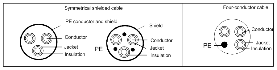
Note: A separate PE conductor is required if the conductivity of the cable shield is not sufficient for the purpose.
To function as a protective conductor, the shield must have the same cross-sectional area as the phase conductors when they are made of the same metal.
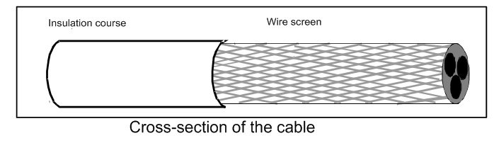
To effectively suppress radiated and conducted radio-frequency emissions, the shield conductivity must be at least 1/10 of the phase conductor conductivity. The requirements are easily met with a copper or aluminum shield. The minimum requirement of the motor cable shield of the drive is shown below. It consists of a concentric layer of copper wires. The better and tighter the shield, the lower the emission level and bearing currents.
D.4.2 Control cables
All analog control cables and the cable used for the frequency input must be shielded. Use a double-shielded twisted pair cable (Figure a) for analog signals. Employ one individually shielded pair for each signal. Do not use common return for different analog signals.
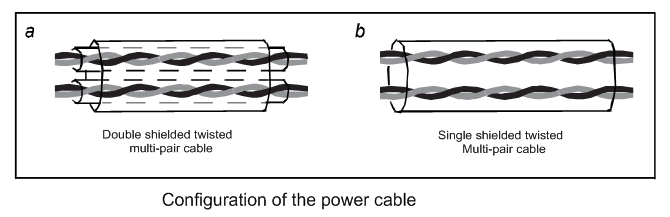
A double-shielded cable is the best alternative for low-voltage digital signals, but a single-shielded or unshielded twisted multi-pair cable (Figure b) is also usable. However, for frequency input, always use a shielded cable.
Note: Run analog and digital signals in separate cables.
The relay cable needs the cable type with braided metallic screen.
The keypad needs to connect with cables. It is recommended to use the screen cable on complex electrical magnetic condition.
Do not make any voltage tolerance or insulation resistance tests (for example hi-pot or megger) on any part of the drive as testing can damage the drive. Every drive has been tested for insulation between the main circuit and the chassis at the factory. Also, there are voltage-limiting circuits inside the drive which cut down the testing voltage automatically.
![]() Check the insulation of the input power cable according to local regulations before connecting to the drive.
Check the insulation of the input power cable according to local regulations before connecting to the drive.
Recommended cable size (mm2) | Required torque (in-lbs) | Wire connector (##) | |||
R,S,T; U,V,W; P1, (+), PB, (-) | PE | R,S,T; U,V,W; P1, (+); PB, (-) | PE | ||
GD310-0R7G-2-UL | 14 | 12 | 11 | 10 | Optional |
GD310-1R5G-2-UL | 12 | 12 | 11 | 10 | Required |
GD310-2R2G-2-UL | 12 | 12 | 11 | 10 | Required |
GD310-004G-2-UL | 8 | 10 | 20 or 25 @@ | 15 | Optional |
GD310-5R5G-2-UL | 8 | 10 | 20 or 25 @@ | 15 | Optional |
GD310-7R5G-2-UL | 6 | 15 | 20 | 8 | Required |
GD310-011G-2-UL | 3 | 8 | 25.5 | 18 | Required |
GD310-015G-2-UL | 3 | 6 | 25.5 | 18 | Required |
GD310-018G-2-UL | 2/0 | 6 | 25.5 | 75 | Required |
GD310-022G-2-UL | 2/0 | 6 | 25.5 | 75 | Required |
GD310-030G-2-UL | 2/0 | 6 | 25.5 | 75 | Required |
GD310-037G-2-UL | 2/0AWG | 1AWG | 60 or 80 $$ | 10 | Required |
GD310-045G-2-UL | 1/0 AWG x 2 | 1 AWG | 90 | 10 | Required |
GD310-055G-2-UL | |||||
GD310-1R5G-4-UL | 14AWG | 12AWG | 11 | 10 | Optional |
GD310-2R2G-4-UL | 14AWG | 12AWG | 11 | 10 | Optional |
GD310-004G-4-UL | 8AWG | 12AWG | 11 | 10 | Required |
GD310-5R5G-4-UL | 8AWG | 10AWG | 11 | 10 | Required |
GD310-7R5G-4-UL | 8AWG | 10AWG | 20 | 15 | Optional |
GD310-011G-4-UL | 8AWG | 10AWG | 20 | 15 | Optional |
GD310-015G-4-UL | 6AWG | 10AWG | 20 | Required | |
GD310-018G-4-UL | 6AWG | 8AWG | 20 | 15 | Required |
GD310-022G-4-UL | 3AWG | 8AWG | 25.5 | 18 | Required |
GD310-030G-4-UL | 3AWG | 6AWG | 25.5 | 18 | Required |
GD310-037G-4-UL | 2/0 | 6AWG | 25.5 | 75 | Required |
GD310-045G-4-UL | 2/0 | 6AWG | 25.5 | 75 | Required |
GD310-055G-4-UL | 2/0 | 6AWG | 25.5 | Required | |
GD310-075G-4-UL | 3/0AWG | 1 AWG | 60 or 80 $$ | 10 | Required |
GD310-090G-4-UL | 1/0 AWG x 2 | 1 AWG | 90 | 10 | Required |
GD310-110G-4-UL | |||||
GD310-132G-4-UL | 350kcmil * 2 | 1 AWG | 338.2 | 338.2 | Optional |
GD310-160G-4-UL | Optional | ||||
GD310-185G-4-UL | Optional | ||||
GD310-200G-4-UL | Optional | ||||
GD310-220G-4-UL | 350kcmil*3 | 4/0AWG | 338.2 | 338.2 | Optional |
GD310-250G-4-UL | Optional | ||||
GD310-280G-4-UL | Optional | ||||
GD310-315G-4-UL | Optional | ||||
GD310-350G-4-UL | 350kcmil*4 | 4/0AWG | 338.2 | 338.2 | Optional |
GD310-400G-4-UL | Optional | ||||
GD310-500G-4-UL | Optional | ||||
GD310-5R5P-4-UL | 8AWG | 10AWG | 11 | 10 | Required |
GD310-7R5P-4-UL | 8AWG | 10AWG | 11 | 10 | Required |
GD310-011P-4-UL | 8AWG | 10AWG | 20 | 15 | Optional |
GD310-015P-4-UL | 8AWG | 10AWG | 20 | 15 | Optional |
GD310-018P-4-UL | 6AWG | 8AWG | 20 | 15 | Required |
GD310-022P-4-UL | 6AWG | 8AWG | 20 | 15 | Required |
GD310-030P-4-UL | 3AWG | 8AWG | 25.5 | 18 | Required |
GD310-037P-4-UL | 3AWG | 6AWG | 25.5 | 18 | Required |
GD310-045P-4-UL | 2/0 | 6AWG | 25.5 | 75 | Required |
GD310-055P-4-UL | 2/0 | 6AWG | 25.5 | 75 | Required |
GD310-075P-4-UL | 3/0AWG | 1 AWG | 60 or 80 $$ | 10 | Required |
GD310-090P-4-UL | |||||
GD310-110P-4-UL | 1/0 AWG x 2 | 1 AWG | 90 | 10 | Required |
GD310-132P-4-UL | 350kcmil x 2 | 1 AWG | 338.2 | 338.2 | Optional |
GD310-160P-4-UL | Optional | ||||
GD310-185P-4-UL | Optional | ||||
GD310-200P-4-UL | Optional | ||||
GD310-220P-4-UL | Optional | ||||
GD310-250P-4-UL | 350kcmil*3 | 2/0AWG | 338.2 | 338.2 | Optional |
GD310-280P-4-UL | Optional | ||||
GD310-315P-4-UL | Optional | ||||
GD310-350P-4-UL | Optional | ||||
GD310-400P-4-UL | 350kcmil*4 | 4/0AWG | 338.2 | 338.2 | Optional |
GD310-500P-4-UL | Optional | ||||
GD310-018G-6-UL | 4AWG | 8AWG | 10 | Required | |
GD310-022G-6-UL | |||||
GD310-030G-6-UL | |||||
GD310-037G-6-UL | |||||
GD310-045G-6-UL | 3/0AWG | 2AWG | 60 | 10 | Required |
GD310-055G-6-UL | |||||
GD310-075G-6-UL | |||||
GD310-090G-6 -UL | |||||
GD310-110G-6-UL | |||||
Control terminal block | 26-14 (Str/Sol) AWG | -- | 4.5 | -- | Optional |
Note:
1. It is appropriate to use the recommended cable size under 40°C and rated current. The wiring distance should be no more than 100m.
2. Terminals P1, (+), PB and (-) connects the DC reactor options and parts.
3. Use 75°C CU wire only for field input and output wire.
4. Note ‘@@’: For Fame Size H1 using SUCCEED’s Terminal Block: “Tightening Torque shall be 22 in-lb” or equivalent.
For Fame Size H1 using DEGSON’s Terminal Block: “Tightening Torque shall be 60 in-lb” Or equivalent.
For Fame Size H1 using CONNECTION’s Terminal Block: “Tightening Torque shall be 49.5 in-lb” or equivalent.
5. Note ‘$$’: For Model G340-01800UL-01 and G320-01300UL-01 using SUCCEED’s Terminal Block: “Tightening Torque shall be 60 in-lb” Or equivalent.
For Model G340-01800UL-01 and G320-01300UL-01 using DEGSON’s Terminal Block: “Tightening Torque shall be 80 in-lb” Or equivalent.
6. Note ‘##’: UL listed wire connector shall be used.
D.4.3 Routing the cables
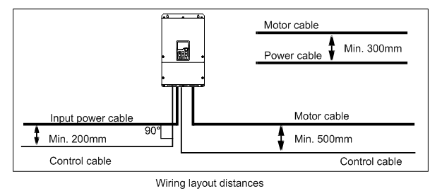
Route the motor cable away from other cable routes. Motor cables of several drives can be run in parallel installed next to each other. It is recommended that the motor cable, input power cable and control cables are installed on separate trays. Avoid long parallel runs of motor cables with other cables to decrease electromagnetic interference caused by the rapid changes in the drive output voltage.
Where control cables must cross power cables make sure that they are arranged at an angle as near to 90 degrees as possible.
The cable trays must have good electrical bonding to each other and to the grounding electrodes. Aluminum tray systems can be used to improve local equalizing of potential.
A figure of the cable routing is shown below.
D.4.4 Insulation checking
Check the insulation of the motor and motor cable as follows:
1. Check that the motor cable is connected to the motor and disconnected from the drive output terminals U, V and W.
2. Measure the insulation resistance between each phase conductor and the Protective Earth conductor using a measuring voltage of 500V DC. For the insulation resistance of other motors, please consult the manufacturer’s instructions.
Note: Moisture inside the motor casing will reduce the insulation resistance. If moisture is suspected, dry the motor and repeat the measurement.