D.8.1 Select the braking components
It is appropriate to use braking resistor or braking unit when the motor brakes sharply or the motor is driven by a high inertia load. The motor will become a generator if its actual rotating speed is higher than the corresponding speed of the reference frequency. As a result, the inertial energy of the motor and load return to the VFD to charge the capacitors in the main DC circuit. When the voltage increases to the limit, damage may occur to the VFD. It is necessary to apply braking unit/resistor to avoid this accident happens.
|
|
| Connect the braking resistor or braking unit with the VFD according to the diagram. Incorrect wiring may cause damage to the VFD or other devices. |


Goodrive310-UL series VFDs below 220V (≤15kW), 460V (G-type≤30kW, P-type≤37kW) need internal braking units and the VFDs 220V (≥18.5kW), 460V (G-type≥37kW, P-type≥45kW) need external braking unit. Please select the resistance and power of the braking resistors according to actual utilization.
The VFDs of 220V (≤15kW), 460V (G-type≤30kW; P-type≤37kW) have embedded braking units but the VFDs of 220V (≥18.5kW), 460V (G-type≥37kW; P-type≥45kW) have optional braking units. Please select the braking resistor according to actual operation.
Model | Model of braking unit | Brake Resistor at 100% of brake torque (Ω) | The consumed power of braking resistor | Min allowable braking resistance (Ω) | ||
10% braking | 50% braking | 80% braking | ||||
Embedded braking unit | 192 | 0.11 | 0.56 | 0.9 | 93 | |
GD310-1R5G-2-UL | 96 | 0.23 | 1.1 | 1.8 | 44 | |
GD310-2R2G-2-UL | 65 | 0.33 | 1.7 | 2.64 | 44 | |
GD310-004G-2-UL | 36 | 0.6 | 3 | 4.8 | 33 | |
GD310-5R5G-2-UL | 26 | 0.75 | 4.13 | 6.6 | 25 | |
GD310-7R5G-2-UL | 19 | 1.13 | 5.63 | 9 | 13 | |
GD310-011G-2-UL | 13 | 1.6 | 8 | 12.8 | 8.8 | |
GD310-015G-2-UL | 9.6 | 2 | 11 | 18 | 6.4 | |
GD310-018G-2-UL | DBU100H-060-2 | 8 | 3 | 14 | 22 | |
GD310-022G-2-UL | DBU100H-110-2 | 6.5 | 3 | 17 | 26 | |
GD310-030G-2-UL | 4.8 | 5 | 23 | 36 | 3.5 | |
GD310-037G-2-UL | 3.9 | 6 | 28 | 44 | ||
GD310-045G-2-UL | DBU100H-160-2 | 3.2 | 7 | 34 | 54 | 2.4 |
GD310-055G-2-UL | 2.6 | 8 | 41 | 66 | ||
GD310-1R5G-4-UL | Embedded braking unit | 326 | 0.23 | 1.1 | 1.8 | 170 |
GD310-2R2G-4-UL | 222 | 0.33 | 1.7 | 2.6 | 130 | |
GD310-004G-4-UL | 122 | 0.6 | 3 | 4.8 | 80 | |
GD310-5R5G-4-UL | 89 | 0.75 | 4.1 | 6.6 | 60 | |
GD310-7R5G-4-UL | 65 | 1.1 | 5.6 | 9 | 47 | |
GD310-011G-4-UL | 44 | 1.7 | 8.3 | 13.2 | 31 | |
GD310-015G-4-UL | 32 | 2 | 11 | 18 | 23 | |
GD310-018G-4-UL | 27 | 3 | 14 | 22 | 19 | |
GD310-022G-4-UL | 22 | 3 | 17 | 26 | 17 | |
GD310-030G-4-UL | 16 | 5 | 23 | 36 | 17 | |
GD310-037G-4-UL | DBU100H-060-4 | 13 | 6 | 28 | 44 | 11.7 |
GD310-045G-4-UL | DBU100H-110-4 | 10 | 7 | 34 | 54 | 6.4 |
GD310-055G-4-UL | 8 | 8 | 41 | 66 | ||
GD310-075G-4-UL | 6.5 | 11 | 56 | 90 | ||
GD310-090G-4-UL | DBU100H-160-4 | 5.4 | 14 | 68 | 108 | 4.4 |
GD310-110G-4-UL | 4.5 | 14 | 83 | 132 | ||
GD310-132G-4-UL | DBU100H-220-4 | 3.7 | 20 | 99 | 158 | 3.2 |
GD310-160G-4-UL | DBU100H-320-4 | 3.1 | 24 | 120 | 192 | 2.2 |
GD310-185G-4-UL | 2.8 | 28 | 139 | 222 | ||
GD310-200G-4-UL | 2.5 | 30 | 150 | 240 | ||
GD310-220G-4-UL | DBU100H-400-4 | 2.2 | 33 | 165 | 264 | 1.8 |
GD310-250G-4-UL | 2.0 | 38 | 188 | 300 | ||
GD310-280G-4-UL | TWO DBU100H-320-4 | 3.6*2 | 21*2 | 105*2 | 168*2 | 2.2*2 |
GD310-315G-4-UL | 3.2*2 | 24*2 | 118*2 | 189*2 | ||
GD310-350G-4-UL | 2.8*2 | 27*2 | 132*2 | 210*2 | ||
GD310-400G-4-UL | 2.4*2 | 30*2 | 150*2 | 240*2 | ||
GD310-500G-4-UL | TWO DBU100H-400-4 | 2*2 | 38*2 | 186*2 | 300*2 | 1.8*2 |
GD310-5R5P-4-UL | 122 | 0.6 | 3 | 4.8 | 80 | |
GD310-7R5P-4-UL | 89 | 0.75 | 4.1 | 6.6 | 60 | |
GD310-011P-4-UL | 65 | 1.1 | 5.6 | 9 | 47 | |
GD310-015P-4-UL | 44 | 1.7 | 8.3 | 13.2 | 31 | |
GD310-018P-4-UL | 32 | 2 | 11 | 18 | 23 | |
GD310-022P-4-UL | 27 | 3 | 14 | 22 | 19 | |
GD310-030P-4-UL | 22 | 3 | 17 | 26 | 17 | |
GD310-037P-4-UL | 16 | 5 | 23 | 36 | 17 | |
GD310-045P-4-UL | DBU100H-060-4 | 13 | 6 | 28 | 44 | 11.7 |
GD310-055P-4-UL | DBU100H-110-4 | 10 | 7 | 34 | 54 | 6.4 |
GD310-075P-4-UL | 8 | 8 | 41 | 66 | ||
GD310-090P-4-UL | 6.5 | 11 | 56 | 90 | ||
GD310-110P-4-UL | DBU100H-160-4 | 5.4 | 14 | 68 | 108 | 4.4 |
GD310-132P-4-UL | 4.5 | 14 | 83 | 132 | ||
GD310-160P-4-UL | DBU100H-220-4 | 3.7 | 20 | 99 | 158 | 3.2 |
GD310-185P-4-UL | DBU100H-320-4 | 3.1 | 24 | 120 | 192 | 2.2 |
GD310-200P-4-UL | 2.8 | 28 | 139 | 222 | ||
GD310-220P-4-UL | 2.5 | 30 | 150 | 240 | ||
GD310-250P-4-UL | DBU100H-400-4 | 2.2 | 33 | 165 | 264 | 1.8 |
GD310-280P-4-UL | 2.0 | 38 | 188 | 300 | ||
GD310-315P-4-UL | TWO DBU100H-320-4 | 3.6*2 | 21*2 | 105*2 | 168*2 | 2.2*2 |
GD310-350P-4-UL | 3.2*2 | 24*2 | 118*2 | 189*2 | ||
GD310-400P-4-UL | 2.8*2 | 27*2 | 132*2 | 210*2 | ||
GD310-500P-4-UL | TWO DBU100H-400-4 | 2.4*2 | 30*2 | 150*2 | 240*2 | 2.2*2 |
GD310-018G-6-UL | DBU100H-110-6 | 55 | 4 | 17 | 27 | 10.0 |
GD310-022G-6-UL | 40.3 | 5 | 23 | 36 | ||
GD310-030G-6-UL | 32.7 | 6 | 28 | 44 | ||
GD310-037G-6-UL | 26.9 | 7 | 34 | 54 | ||
GD310-045G-6-UL | 22.0 | 8 | 41 | 66 | ||
GD310-055G-6-UL | 16.1 | 11 | 56 | 90 | ||
GD310-075G-6-UL | 13.4 | 14 | 68 | 108 | ||
GD310-090G-6-UL | 11.0 | 17 | 83 | 132 | ||
GD310-110G-6-UL | DBU100H-160-6 | 9.2 | 20 | 99 | 158 | 6.9 |
Note:
Select the resistor and power of the braking unit according to the data provided by our company.
The braking resistor may increase the braking torque of the VFD. The resistor power in the above table is designed on 100% braking torque and 10% braking usage ratio. If the users need more braking torque, the braking resistor can decrease properly and the power needs to be magnified.
When using the external braking units, please see the instructions of the energy braking units to set the voltage degree of the braking unit. Incorrect voltage degree may affect the normal running of the VFD.
| Never use a brake resistor with a resistance below the minimum value specified for the particular drive. The drive and the internal chopper are not able to handle the overcurrent caused by the low resistance. |
| Increase the power of the braking resistor properly in the frequent braking situation (the frequency usage ratio is more than 10%). |


D.8.2 Selecting the brake resistor cables
Use a shielded cable to the resistor cable.
D.8.3 Placing the brake resistor
Install all resistors in a place with enough ventilation.
| The materials near the brake resistor must be non-flammable. The surface temperature of the resistor is high. Air flowing from the resistor is of hundreds of degrees Celsius. Protect the resistor against contact. |

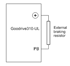
Installation of the braking resistor:
|
|

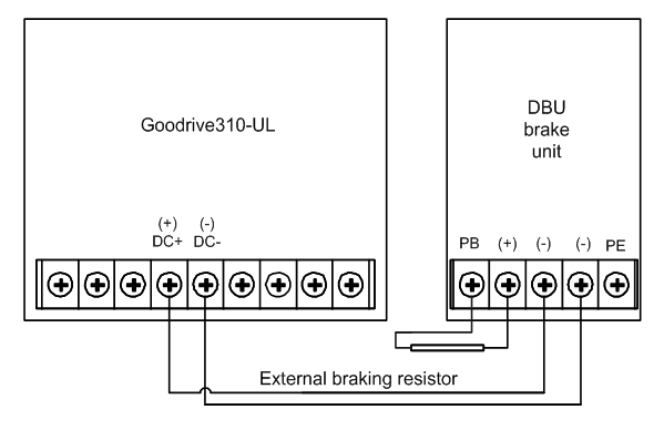
Installation of braking units:
|
|

Signal installation is as below: