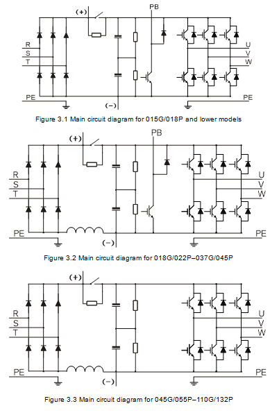
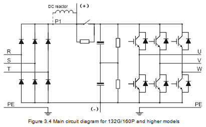
The VFD is used to control asynchronous AC induction motors and permanent-magnet synchronous motors. The figure below shows the main circuit diagram of the VFD. The rectifier converts 3PH AC voltage into DC voltage, and the capacitor bank of intermediate circuit stabilizes the DC voltage. The VFD converts DC voltage into the AC voltage used by AC motor. When the circuit voltage exceeds the maximum limit value, external braking resistor will be connected to intermediate DC circuit to consume the feedback energy.
Note:
l 132G/160P and higher models can be connected to external DC reactors. Before connection, take off the copper bar between P1 and (+). 075G/090P and higher models can be connected to external braking units. DC reactors and braking units are optional parts.
l 018G/022P–110G/132P models are equipped with built-in DC reactors.
l 037G/045P and lower models carry built-in braking units. Braking units are optional parts for 045G/055P–055G/075P models and they can be built in or externally connected to the models.