The VFD structure is shown in the following figure (using the 030G/037P VFD model as an example):
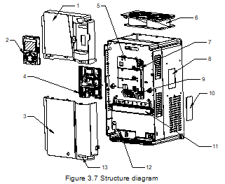
No. | Item | Description |
1 | Upper cover | Used to protect internal components. |
2 | Keypad | For details, see "Operating the VFD by keypad". |
3 | Lower cover | Used to protect internal components. |
4 | Expansion card | Optional. For details, see "Expansion cards". |
5 | Control board baffle | Used to protect the control board and install expansion cards. |
6 | Cooling fan | For details, see "Maintenance". |
7 | Keypad interface | Used to connect the keypad. |
8 | Nameplate | See "Product nameplate". |
9 | Control terminals | See "Installation guidelines". |
10 | Ventilation hole cover | Optional. Using the ventilation hole cover can enhance the protection rating but also increase the internal temperature, which requires derating. |
11 | Main circuit terminals | For details, see "Installation guidelines". |
12 | POWER indicator | Indicator of the power supply. |
13 | GD350A product series label | See "Model designation code". |