4.2.1 Installation environment
Installation environment is essential for the VFD to operate at its best in the long run. The installation environment of the VFD should meet the following requirements.
Environment | Condition |
Installation site | Indoors |
Ambient temperature | ² -10–+50°C; ² When the ambient temperature exceeds 40°C, derate 1% for every additional 1°C; ² It is not recommended to use the VFD when the ambient temperature is above 50°C; ² In order to improve reliability, do not use the VFD in cases where the temperature changes rapidly; ² When the VFD is used in a closed space e.g. control cabinet, use cooling fan or air conditioner to prevent internal temperature from exceeding the temperature required; ² When the temperature is too low, if restart an VFD which has been idled for a long time, it is required to install external heating device before use to eliminate the freeze inside the VFD, failing to do so may cause damage to the VFD. |
Humidity | ² The relative humidity (RH) of the air is less than 90%; ² Condensation is not allowed; ² The max RH cannot exceed 60% in the environment where there are corrosive gases. |
Storage temperature | -30–+60°C |
Running environment | The installation site should meet the following requirements. ² Away from electromagnetic radiation sources; ² Away from oil mist, corrosive gases and combustible gases; ² Ensure foreign object like metal powder, dust, oil and water will not fall into the VFD (do not install the VFD onto combustible object like wood); ² Away from radioactive substance and combustible objects; ² Away from harmful gases and liquids; ² Low salt content; ² No direct sunlight |
Altitude | ² Below 1000m; ² When the altitude exceeds 1000m, derate 1% for every additional 100m; ² When the altitude exceeds 2000m, configure isolation transformer on the input end of the VFD. It is recommended to keep the altitude below 5000m. |
Vibration | The max. amplitude of vibration should not exceed 5.8m/s2 (0.6g) |
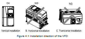
Installation direction | Install the VFD vertically to ensure good heat dissipation effect |
Note:
l The VFD must be installed in a clean and well-ventilated environment based on the IP level.
l The cooling air must be clean enough and free from corrosive gases and conductive dust.
4.2.2 Installation direction
The VFD can be installed on the wall or in a cabinet.
The VFD must be installed vertically. Check the installation position according to following requirements. See Appendix C Dimension drawings.
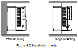
4.2.3 Installation mode
There are three kinds of installation modes based on different VFD dimensions.
l Wall-mounting: suitable for 315G/355P and lower models
l Flange-mounting: suitable for 200G/220P and lower models
l Floor-mounting: suitable for 220G/250P–500G models
(1) Mark the position of the installation hole. See appendix for the position of installation hole;
(2) Mount the screws or bolts onto the designated position;
(3) Put the VFD on the wall;
(4) Tighten the fixing screws on the wall.
Note:
l The flange-mounting plate is a must for 1R5G/2R2P–075G/090P models that adopt flange-mounting mode; while 090G/110P–200G/220P models need no flange-mounting plate.
l The installation base is optional for 220G/250P–315G/355P models. The base can hold an input AC reactor (or DC reactor) and an output AC reactor.
4.2.4 Single-unit installation
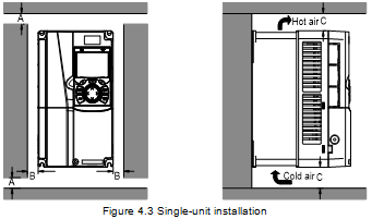
Note: The min. dimension of B and C is 100mm.
4.2.5 Multiple-unit installation
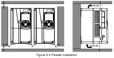
Note:
l When you install VFDs in different sizes, align the top of each VFD before installation for the convenience of future maintenance.
l The min. dimension of B, D and C is 100mm.
4.2.6 Vertical installation
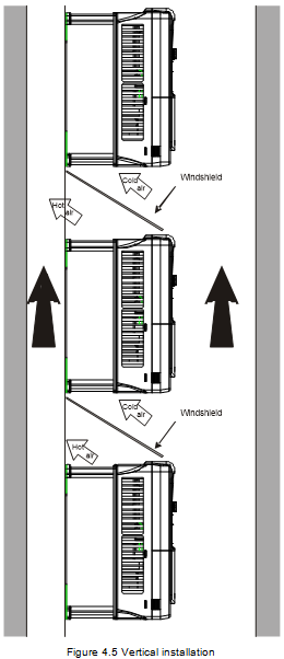
Note: During vertical installation, you must install windshield, otherwise, the VFD will experience mutual interference, and the heat dissipation effect will be degraded.
4.2.7 Tilted installation
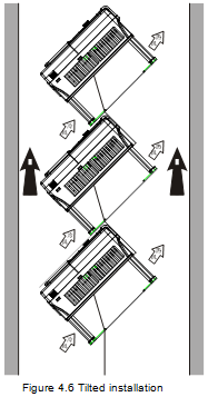
Note: During tilted installation, it is a must to ensure the air inlet duct and air outlet duct are separated from each other to avoid mutual interference.