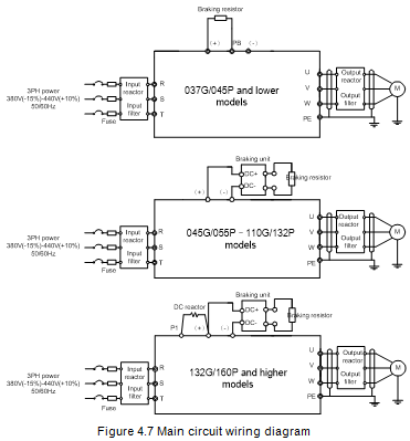
4.3.1 Main circuit wiring diagram
Note:
l The fuse, DC reactor, braking unit, braking resistor, input reactor, input filter, output reactor and output filter are optional parts. See Appendix D Optional peripheral accessories.
l P1 and (+) have been short connected by default for 132G/160P and higher models. If you need to connect to external DC reactor, take off the short-contact tag of P1 and (+).
l When connecting the braking resistor, take off the yellow warning sign marked with PB, (+) and (-) on the terminal block before connecting the braking resistor wire, otherwise, poor contact may occur.
l Braking units are optional parts for 045G/055P–055G/075P models, and they can be built in or externally connected to the models.
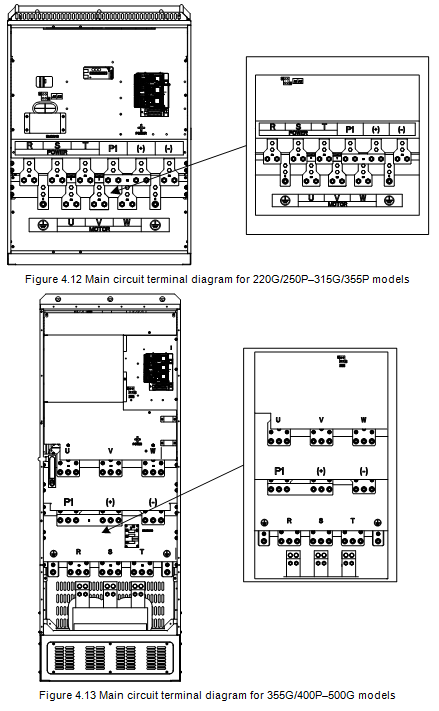
4.3.2 Main circuit terminal diagram
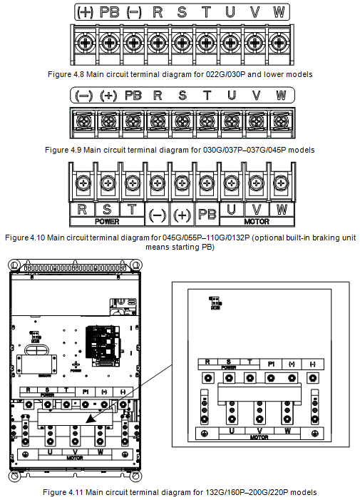
Sign | Terminal | Function description | |||
037G/045P and lower | 045G/055P–110G/132P | 132G/160P and higher | |||
R, S, T | Main circuit power input | 3PH AC input terminal, connected to the grid. | |||
U, V, W | VFD output | 3PH AC output terminal, connected to the motor in most cases. | |||
P1 | Not available | Not available | DC reactor terminal 1 | P1 and (+) connect to external DC reactor terminals. (+) and (-) connect to external braking unit terminals. PB and (+) connect to external braking resistor terminals. | |
(+) | Braking resistor terminal 1 | Braking unit terminal 1 Braking resistor terminal 1 | DC reactor terminal 2 Braking unit terminal 1 | ||
(-) | / | Braking unit terminal 2 | |||
PB | Braking resistor terminal 2 | Braking resistor terminal 2 | Not available | ||
PE | Grounding resistor less than 10Ω | Grounding terminal for safe protection; each machine must carry two PE terminals and proper grounding is required. | |||
Note:
l Do not use asymmetrical motor cables. If there is a symmetrical grounding conductor in the motor cable besides the conductive shielded layer, ground the grounding conductor on the VFD end and motor end.
l Braking resistor, braking unit and DC reactor are optional parts.
l Route the motor cables, input power cables and control cables separately.
l "Not available" means this terminal is not for external connection.
l The PB is available for the 045G/055P–110G/132P models only when built-in braking units have been selected for the 045G/055P–055G/75P models.
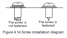
4.3.3 Wiring procedure of the main circuit terminals
1. Connect the ground wire of the input power cable to the PE terminal of the VFD, connect the 3PH input cable to the R, S and T terminals, and tighten up.
2. Connect the ground wire of the motor cable to the PE terminal of the VFD, connect the motor 3PH cable to the U, V and W terminals, and tighten up.
3. Connect optional parts such as the braking resistor that carries cables to designated positions.
4. Fasten all the cables outside the VFD mechanically if allowed.