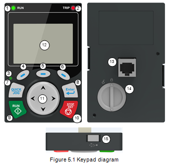
The VFD has been equipped with the LCD keypad as a standard configuration part. You can use the keypad to control the start and stop, read status data, and set parameters of the VFD.
Note:
l The LCD keypad is equipped with a real-time clock, which can run properly after being installed with batteries even if the power line is disconnected. The clock battery (type: CR2032) is user purchased.
l The LCD keypad has the parameter copying function.
l If you need install the keypad on another position rather than on the VFD, use M3 screws or a keypad installation bracket for fixing, and use a keypad extension cable with a standard RJ45 crystal head.
Item | Description | |||
Status indicator | 1 | RUN | VFD running status indicator. LED off: The VFD is stopped. LED blinking: The VFD is autotuning parameters. LED on: The VFD is running. | |
2 | TRIP | Fault indicator. LED on: in fault state LED off: in normal state LED blinking: in pre-alarm state | ||
3 | QUICK/JOG | Short-cut key indicator, which displays different state under different functions, see definition of the QUICK/JOG key for details. | ||
Key area | 4 |
| Function key | The function of function key varies with the menu; The function of function key is displayed in the footer. |
5 |
| |||
6 |
| |||
7 |  | Short-cut key | Re-definable. It is defined as JOG function by default, namely jogging. The function of short-cut key can be set by the ones of P07.12, as shown in the following. 0: No function 1: Jogging (linkage indicator 3; logic : NO); 2: Reserved 3: FWD/REV switch-over (linkage indicator 3; logic: NC) 4: Clear UP/DOWN setting (linkage indicator 3 logic: NC) 5: Coast to stop (linkage indicator 3; logic: NC) ; 6: Switching running command reference mode in order (linkage indicator 3; logic: NC) 7: Reserved Note: After restoring to default values, the default function of short-cut key 7 is 1. | |
8 |
| Confirmation key | The function of the confirmation key varies with menus, such as confirming parameter setting, confirming parameter selection, and entering the next menu. | |
9 |
| Run key | When the VFD is controlled by the keypad, this key is used to run the VFD or perform autotuning. | |
10 |
| Stop/ Reset key | In running state, pressing this key can stop running or autotuning; this key is limited by P07.04. In fault alarm state, all the control modes can be reset by this key. | |
11 |
|
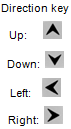
| Up: Its function varies with the interface (Example: shifting up the displayed/selected item and changing digits) Down: Its function varies with the interface (Example: shifting down the displayed/selected item and changing digits) Left: Its function varies with the interface (Example: switching the monitoring interface, shifting the cursor leftward, and returning to the previous menu) Right: Its function varies with the interface (Example: switching the monitoring interface, shifting the cursor rightward, and entering the next menu) | |
Display area | 12 | LCD | Display screen | 240*160 dot-matrix LCD, able to display three monitoring parameters or six sub-menu items simultaneously. |
Other | 13 | RJ45 interface | RJ45 interface | The RJ45 interface is used to connect to the VFD. |
14 | Battery cover | Clock battery cover | To replace or mount the clock battery, remove this cover, and then close the cover after the battery is mounted. | |
15 | USB terminal | Mini USB terminal | The mini USB terminal is used to connect to the USB flash drive through an adapter. | |


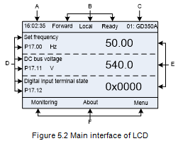
The LCD has different display areas, which show different contents under different interfaces. The following figure shows the main interface in stop state.
Area | Name | Displayed contents |
Header A | Real-time display area | Display the real-time; clock battery is not included; the time needs to be reset when powering on the VFD. |
Header B | VFD running state display area | Display the running state of the VFD: 1. Display motor rotating direction: "Forward" – Run forward during operation; Reverse – Run reversely during operation; "Forbid" – Reverse running is forbidden; 2. Display VFD running command channel: "Local" – Keypad; "Terminal" – Terminal; "Remote" - Communication 3. Display current running state of the VFD : "Ready" – The VFD is in stop state (no fault); "Run" – The VFD is in running state; "Jog" – The VFD is in jogging state; "Pre-alarm" – the VFD is under pre-alarm state during running; "Fault" – VFD fault occurred. |
Header C | VFD station no. and model display area | 1. Display VFD station no.: 01–99, applied in multi-drive applications (reserved function); 2. VFD model display: "GD350A" – current VFD is GD350A series VFD |
Display D | The parameter name and function code monitored by the VFD | Display the parameter name and corresponding function code monitored by the VFD; three monitoring parameters can be displayed simultaneously. The monitoring parameter list can be edited. |
Display E | Parameter value monitored by the VFD | Display the parameter value monitoring by the VFD, the monitoring value will be refreshed in real time |
Footer F | Corresponding menus of function keys 4, 5 and 6 | Corresponding menus of function keys 4, 5 and 6. The corresponding menus of function keys 4, 5 and 6 vary with interfaces, and the contents displayed in this area are also different. |