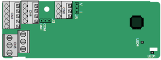
The terminals are arranged as follows:
CME and COM are shorted through J3 before delivery, and J5 is the jumper for selecting the output type (voltage or current) of AO2.
Indicator definition:
Indicator | Name | Function |
LED1 | State indicator | This indicator is on when the expansion card is establishing a connection with the control board; it blinks periodically after the expansion card is properly connected to the control board (the period is 1s, on for 0.5s, and off for the other 0.5s); and it is off when the expansion card is disconnected from the control board. |
LED4 | Power indicator | This indicator is on after the IO expansion card is powered on by the control board. |
The EC-IO501-00 expansion card can be used in scenarios where the I/O interfaces of the VFD cannot meet the application requirements. It can provide 4 digital inputs, 1 digital output, 1 analog input, 1 analog output, and two relay outputs. It is user-friendly, providing relay outputs through European-type screw terminals and other inputs and outputs through spring terminals.
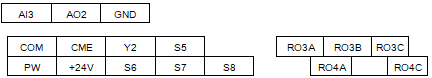
EC-IO501-00 terminal function description:
Category | Sign | Name | Function |
Power | PW | External power supply | The working power of digital input is provided by an external power supply. Voltage range: 12–24 V The terminals PW and +24V are shorted before delivery. |
Analog input/output | AI3—GND | Analog input 1 | 1. Input range: 0–10 V, 0–20 mA 2. Input impedance: 20 kΩ for voltage input; 250 Ω for current input 3. Set it to be voltage or current input through the corresponding function code. 4. Resolution: When 10 V corresponds to 50 Hz, the minimum resolution is 5 mV. 5. Deviation:±0.5%; input of 5 V or 10 mA or higher at the temperature of 25°C |
AO2—GND | Analog output 1 | 1. Output range: 0–10 V, 0–20 mA 2. Whether it is voltage or current output is determined by J5. 3. Deviation ±0.5%; input of 5 V or 10 mA or higher at the temperature of 25°C | |
Digital input/output | S5—COM | Digital input 1 | 1. Internal impedance: 3.3 kΩ 2. Power input range: 12–30 V 3. Bidirectional input terminal 4. Max. input frequency: 1 kHz |
S6—COM | Digital input 2 | ||
S7—COM | Digital input 3 | ||
S8—COM | Digital input 4 | ||
Y2—CME | Digital output | 1. Switch capacity: 200 mA/30 V 2. Output frequency range: 0–1 kHz 3. The terminals CME and COM are shorted through J3 before delivery. | |
Relay output | RO3A | NO contact of relay 3 | 1. Contact capacity: 3A/AC 250 V, 1 A/DC 30 V 2. Do not use them as high-frequency digital outputs. |
RO3B | NC contact of relay 3 | ||
RO3C | Common contact of relay 3 | ||
RO4A | NO contact of relay 4 | ||
RO4C | Common contact of relay 4 |