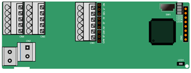
The terminals are arranged as follows:
SW1 is the start/stop switch of the programmable expansion card. CN1 contains terminals PE, 485-, 485+, GND, AI1, and AO1, and a selection jumper resides on the next. "AI" and "AV" are the current type input selection and voltage type input selection of AI1, and they can be selected through J2. "AIO" and "AVO" are the current type output selection and voltage type output selection of AO1, and they can be selected through J5. "120" indicates 120Ω terminal resistor, and it can connect to J1. By default, J1 connects to NC, J2 to AV, and J5 to AVO.
Indicator definition:
Indicator | Name | Function |
LED1 | Power indicator (Green) | This indicator is on when the expansion card is powered on. |
LED3 | Communication indicator (Green) | This indicator is on when the expansion card is establishing a connection with the control board; it blinks periodically after the expansion card is properly connected to the control board (the period is 1s, on for 0.5s, and off for the other 0.5s); and it is off when the expansion card is disconnected from the control board. |
LED4 | Error indicator (Red) | This indicator blinks when an error occurs (the blinking period is 1s, on for 0.5s, and off for the other 0.5s). You can query the error types on the upper computer Auto Station. This indicator is off when there is no error. |
LED5 | Power indicator | This indicator is on when the expansion card is powered on. |
LED6 | RUN indicator (Green) | This indicator is on when the PLC program is running; it is off when the PLC program stops. |
The EC-PC502-00 programmable expansion card can replace some micro PLC applications. It adopts the global mainstream development environment PLC, supporting the instruction language (IL), ladder diagram (LD), and sequential function chart (SFC). It provides a user program storage space of 16K steps and data storage space of 8K words, and supports saving data of 1K words at power failure, which facilitate customers' secondary development and meets the customization requirements.
The EC-PC502-00 programmable expansion card provides 6 digital inputs, 2 relay outputs, 1 analog input, 1 analog output, and 1 RS485 communication channel (for master/slave switchover). It is user-friendly, providing relay outputs through European-type screw terminals and other inputs and outputs through spring terminals.
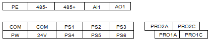
EC-PC502-00 terminal function description:
Category | Sign | Name | Function |
Power | PW | External power | The working power of digital input is provided by an external power supply. Voltage range: 12–24 V The terminals PW and +24V are shorted before delivery. |
24V | Internal power | Internal output power: 100mA | |
Digital input/output | PS1—COM | Digital input 1 | 1. Internal impedance: 4 kΩ 2. Allowable voltage input: 12–30 V 3. Bidirectional terminal 4. Max. input frequency: 1 kHz 5. Supporting both source type input and sink type input, but the input type must be the same |
PS2—COM | Digital input 2 | ||
PS3—COM | Digital input 3 | ||
PS4—COM | Digital input 4 | ||
PS5—COM | Digital input 5 | ||
PS6—COM | Digital input 6 | ||
PY1—CME | Digital output 1 | 1. Switch capacity: 200 mA/30 V 2. Output frequency range: 0–1 kHz 3. The terminals CME and COM are shorted through J1 before delivery. | |
PY2—CME | Digital output 2 | ||
Analog input/output | AI1 | Analog input 1 | 1. Input range: 0~10V or 0~20mA 2. Input resistance: 20kΩ for voltage input, and 250kΩ for current input 3. Whether the input is the voltage or current type is set through the jumper. 4. Resolution: When 10V corresponds to 50Hz, the min. resolution is 5mV. 5. Deviation ±1%, 25°C, full measuring range |
AO1 | Analog output 1 | 1. Output range: 0~10V voltage or 0~20mA current 2. Whether the output is the voltage or current type is set through the jumper. 3. Deviation ±1%, 25°C, full measuring range | |
Relay output | PRO1A | NO contact of relay 1 | 1. Contact capacity: 3A/AC 250 V, 1 A/DC 30 V 2. Do not use them as high-frequency digital outputs. |
PRO1B | NC contact of relay 1 | ||
PRO1C | Common contact of relay 1 | ||
PRO2A | NO contact of relay 2 | ||
PRO2C | Common contact of relay 2 |
For details about the operation of programmable expansion cards, see the Goodrive350 Series VFD Auto Station Programmable Expansion Card Operation Manual.