A.7.1 Sin/Cos PG card——EC-PG502
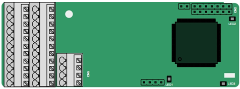
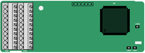
The terminals are arranged as follows:
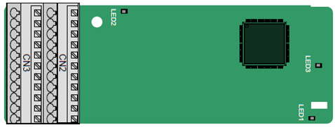
PE | AO+ | BO+ | ZO+ | A1+ | B1+ | R1+ | A2+ | B2+ | Z2+ | PWR |
GND | AO- | BO- | ZO- | A1- | B1- | R1- | A2- | B2- | Z2- | GND |
C1+ | C1- | D1+ | D1- |
Indicator definition:
Indicator | Name | Function |
LED1 | Disconnection indicator | This indicator is off when A1 and B1 of the encoder are disconnected; it blinks when C1 and D1 of the encoder are disconnected; and it is on the encoder signals are normal. |
LED2 | Power indicator | This indicator is on after the control board feeds power to the PG card. |
LED3 | State indicator | This indicator is on when the expansion card is establishing a connection with the control board; it blinks periodically after the expansion card is properly connected to the control board (the period is 1s, on for 0.5s, and off for the other 0.5s); and it is off when the expansion card is disconnected from the control board. |
EC-PG502 terminal function description:
Signal | Port | Function |
PWR | Encoder power | Voltage: 5 V ± 5% Max. output current: 150 mA |
PGND | ||
A1+ | Encoder interface | 1. Supporting Sin/Cos encoders 2. SINA/SINB/SINC/SIND 0.6–1.2Vpp; SINR 0.2–0.85Vpp 3. Max. frequency response of A/B signals: 200 kHz Max. frequency response of C/D signals: 1 kHz |
A1- | ||
B1+ | ||
B1- | ||
R1+ | ||
R1- | ||
C1+ | ||
C1- | ||
D1+ | ||
D1- | ||
A2+ | Pulse reference | 1. Supporting interfaces whose signal type is the same as the encoder 2. Frequency response: 200 kHz |
A2- | ||
B2+ | ||
B2- | ||
Z2+ | ||
Z2- | ||
AO+ | Frequency-divided output | 1. Differential output of 5 V 2. Supporting frequency division of 2N, which can be set through P20.16 or P24.16; Max. output frequency: 200 kHz |
AO- | ||
BO+ | ||
BO- | ||
ZO+ | ||
ZO- |
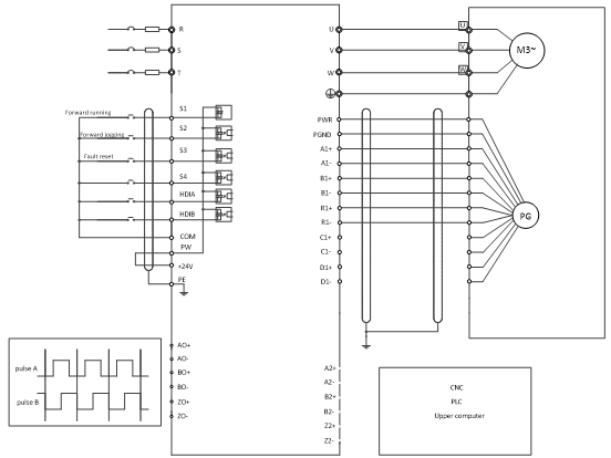
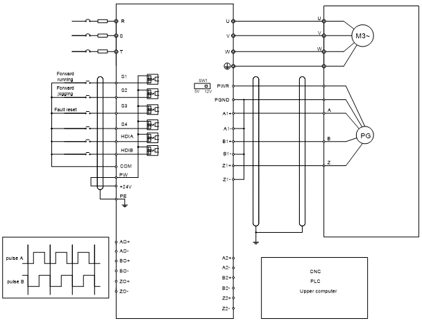
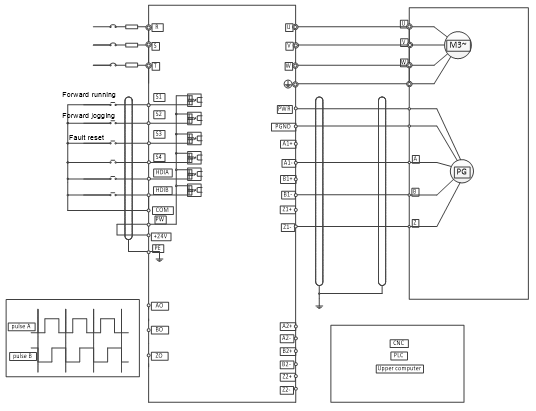
The following figure shows the external wiring of the PG card when it is used in combination with an encoder without CD signals.
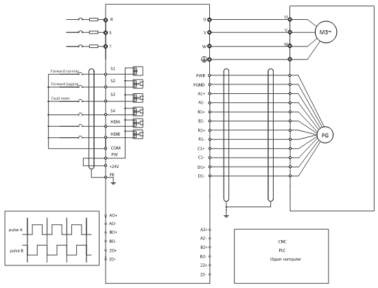
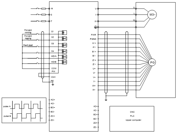
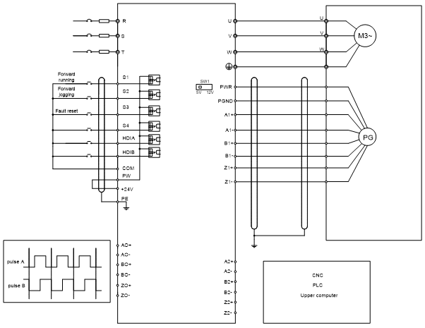
The following figure shows the external wiring of the PG card when it is used in combination with an encoder with CD signals.
A.7.2 UVW incremental PG card——EC-PG503-05
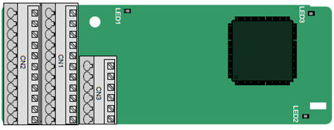
The terminals are arranged as follows:
A2+ | A2- | B2+ | B2- | Z2+ | Z2- | |||||
PE | AO+ | BO+ | ZO+ | A1+ | B1+ | Z1+ | U+ | V+ | W+ | PWR |
GND | AO- | BO- | ZO- | A1- | B1- | Z1- | U- | V- | W- | PGND |
Indicator definition:
Indicator | Name | Function |
LED1 | State indicator | This indicator is on when the expansion card is establishing a connection with the control board; it blinks periodically after the expansion card is properly connected to the control board (the period is 1s, on for 0.5s, and off for the other 0.5s); and it is off when the expansion card is disconnected from the control board. |
LED2 | Disconnection indicator | This indicator is off when A1 and B1 of the encoder is disconnected; and it is on when the pulses are normal. |
LED3 | Power indicator | This indicator is on after the control board feeds power to the PG card. |
The EC-PG503-05 expansion card supports the input of absolute position signals and integrates the advantages of absolute and incremental encoders. It is user-friendly, adopting spring terminals.
EC-PG503-05 terminals are described as follows:
Signal | Port | Function |
PWR | Encoder power | Voltage: 5 V±5% Max. current: 200 mA |
PGND | ||
A1+ | Encoder interface | 1. Differential incremental PG interface of 5 V 2. Response frequency: 400 kHz |
A1- | ||
B1+ | ||
B1- | ||
Z1+ | ||
Z1- | ||
A2+ | Pulse setting | 1. Differential input of 5 V 2. Response frequency: 200 kHz |
A2- | ||
B2+ | ||
B2- | ||
Z2+ | ||
Z2- | ||
AO+ | Frequency-divided output | 1. Differential output of 5 V 2. Supporting frequency division of 1–255, which can be set through P20.16 or P24.16 |
AO- | ||
BO+ | ||
BO- | ||
ZO+ | ||
ZO- | ||
U+ | UVW encoder interface | 1. Absolute position (UVW information) of the hybrid encoder, differential input of 5 V 2. Response frequency: 40 kHz |
U- | ||
V+ | ||
V- | ||
W+ | ||
W- |
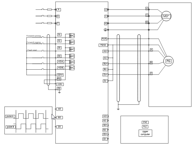
The following figure shows the external wiring of the EC-PG503-05 expansion card.
A.7.3 Resolver PG card——EC-PG504-00
PE | AO+ | BO+ | ZO+ | EX+ | SI+ | CO+ | A2+ | B2+ | Z2+ | PWR |
GND | AO- | BO- | ZO- | EX- | SI- | CO- | A2- | B2- | Z2- | PGND |
Indicator definition:
Indicator | Name | Function |
LED1 | Status indicator | This indicator is on when the expansion card is establishing a connection with the control board; it blinks periodically after the expansion card is properly connected to the control board (the period is 1s, on for 0.5s, and off for the other 0.5s); and it is off when the expansion card is disconnected from the control board. |
LED2 | Disconnection indicator | This indicator is off when the encoder is disconnected; it is on when the encoder signals are normal; and it blinks when the encoder signals are not stable. |
LED3 | Power indicator | This indicator is on after the control board feeds power to the PG card. |
The EC-PG504-00 expansion card can be used in combination with a resolver of excitation voltage 7 Vrms. It is user-friendly, adopting spring terminals.
EC-PG504-00 terminals are described as follows:
Signal | Port | Function |
SI+ | Encoder signal input | Recommended resolver transformation ratio: 0.5 |
SI- | ||
CO+ | ||
CO- | ||
EX+ | Encoder excitation signal | 1. Factory setting of excitation: 10 kHz 2. Supporting resolvers with an excitation voltage of 7 Vrms |
EX- | ||
A2+ | Pulse setting | 1. Differential input of 5 V 2. Response frequency: 200 kHz |
A2- | ||
B2+ | ||
B2- | ||
Z2+ | ||
Z2- | ||
AO+ | Frequency-divided output | 1. Differential output of 5 V 2. Frequency-divided output of resolver simulated A1, B1, and Z1, which is equal to an incremental PG card of 1024 pps. 3. Supporting frequency division of 1–255, which can be set through P20.16 or P24.16 4. Max. output frequency: 200 kHz |
AO- | ||
BO+ | ||
BO- | ||
ZO+ | ||
ZO- |
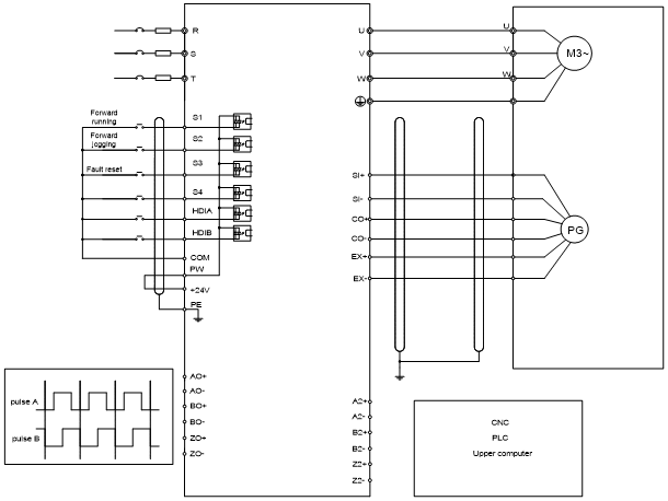
The following figure shows the external wiring of the EC-PG504-00 expansion card.
A.7.4 Multifunction incremental PG card——EC-PG505-12
The terminals are arranged as follows:
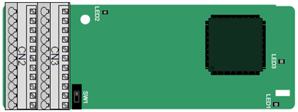
The dual in-line package (DIP) switch SW1 is used to set the voltage class (5 V or 12 V) of the power supply of the encoder. The DIP switch can be operated with an auxiliary tool.
PE | AO+ | BO+ | ZO+ | A1+ | B1+ | Z1+ | A2+ | B2+ | Z2+ | PWR |
GND | AO- | BO- | ZO- | A1- | B1- | Z1- | A2- | B2- | Z2- | PGND |
Indicator definition:
Indicator | Name | Function |
LED1 | Status indicator | This indicator is on when the expansion card is establishing a connection with the control board; it blinks periodically after the expansion card is properly connected to the control board (the period is 1s, on for 0.5s, and off for the other 0.5s); and it is off when the expansion card is disconnected from the control board. |
LED2 | Disconnection indicator | This indicator is off when A1 and B1 of the encoder is disconnected; and it is on when the pulses are normal. |
LED3 | Power indicator | This indicator is on after the control board feeds power to the PG card. |
The EC-PG505-12 expansion card can be used in combination with multiple types of incremental encoders through different modes of wiring. It is user-friendly, adopting spring terminals.
EC-PG505-12 terminal function description:
Signal | Port | Function |
PWR | Encoder power | Voltage: 5 V/12 V ±5% Max. output: 150 mA Select the voltage class through the DIP switch SW1 based on the voltage class of the used encoder. |
PGND | ||
A1+ | Encoder interface | 1. Supporting push-pull interfaces of 5 V/12 V 2. Supporting open collector interfaces of 5 V/12 V 3. Supporting differential interfaces of 5 V 4. Response frequency: 200 kHz |
A1- | ||
B1+ | ||
B1- | ||
Z1+ | ||
Z1- | ||
A2+ | Pulse setting | 1. Supporting the same signal types as the encoder signal types 2. Response frequency: 200 kHz |
A2- | ||
B2+ | ||
B2- | ||
Z2+ | ||
Z2- | ||
AO+ | Frequency-divided output | 1. Differential output of 5 V 2. Supporting frequency division of 1–255, which can be set through P20.16 or P24.16 |
AO- | ||
BO+ | ||
BO- | ||
ZO+ | ||
ZO- |
The following figure shows the external wiring of the expansion card used in combination with an open collector encoder. A pull-up resistor is configured inside the PG card.
The following figure shows the external wiring of the expansion card used in combination with a push-pull encoder.

The following figure shows the external wiring of the expansion card used in combination with a differential encoder.
A.7.5 24V multi-function incremental PG card——EC-PG505-24
The terminals are arranged as follows:
PE | AO | BO | A1+ | B1+ | Z1+ | A2+ | B2+ | Z2+ | PWR |
GND | PGND | ZO | A1- | B1- | Z1- | A2- | B2- | Z2- | PGND |
Indicator definition:
Indicator | Name | Function |
LED1 | State indicator | This indicator is on when the expansion card is establishing a connection with the control board; it blinks periodically after the expansion card is properly connected to the control board (the period is 1s, on for 0.5s, and off for the other 0.5s); and it is off when the expansion card is disconnected from the control board. |
LED2 | Disconnection indicator | This indicator is off when A1 and B1 of the encoder are disconnected; it is on when the encoder pulses are normal; and it blinks when an exception occurs in the communication between the encoder and control board. |
LED3 | Power indicator | This indicator is on after the control board feeds power to the PG card. |
EC-PG505-24 can work in combination with multiple types of incremental encoders through various external wiring modes. It is user-friendly, adopting spring terminals.
EC-PG505-24 terminal function description
Signal | Port | Function |
PWR | Encoder power supply | Voltage: 24 V ± 5% Max. output current: 150 mA |
PGND | ||
A1+ | Encoder interface | 1. Supporting 24 V push-pull interfaces 2. Supporting 24 V open collector interfaces 3. Frequency response: 200 kHz |
A1- | ||
B1+ | ||
B1- | ||
Z1+ | ||
Z1- | ||
A2+ | Pulse reference | 1. Supporting interfaces whose signal type is the same as the encoder 2. Frequency response: 200 kHz |
A2- | ||
B2+ | ||
B2- | ||
Z2+ | ||
Z2- | ||
AO | Frequency-divided output | 1. Open-drain collector output 2. Supporting frequency division of 1–255, which can be set through P20.16 or P24.16 |
BO | ||
ZO |
The following figure shows the external wiring of the PG card when it is used in combination with an open-drain collector encoder. A pull-up resistor is configured in the PG card.
The following figure shows the external wiring of the PG card when it is used in combination with a push-pull encoder.
A.7.6 Simplified incremental PG card——EC-PG507-12
The terminals are arranged as follows:
The DIP switch SW1 is used to set the voltage class (5 V or 12 V) of the power supply of the encoder. The DIP switch can be operated with an auxiliary tool.
PE | A1+ | B1+ | Z1+ | PWR |
PGND | A1- | B1- | Z1- | PGND |
Indicator definition:
Indicator | Name | Function |
LED1 | Status indicator | This indicator is on when the expansion card is establishing a connection with the control board; it blinks periodically after the expansion card is properly connected to the control board (the period is 1s, on for 0.5s, and off for the other 0.5s); and it is off when the expansion card is disconnected from the control board. |
LED2 | Disconnection indicator | This indicator is off when A1 and B1 of the encoder are disconnected; it is on when the encoder pulses are normal. |
LED3 | Power indicator | This indicator is on after the control board feeds power to the PG card. |
EC-PG507-12 can work in combination with multiple types of incremental encoders through various external wiring modes, which are similar to the wiring modes of EC-PG505-12.
EC-PG507-12 terminals are described as follows:
Signal | Port | Function |
PWR | Encoder power | Voltage: 5V/12V ± 5% Max. current: 150 mA The voltage class can be selected through SW1, depending on the encoder voltage class. (PGND is the isolation power ground.) |
PGND | ||
A1+ | Encoder interface | 1. Supporting push-pull interfaces of 5 V/12 V 2. Supporting open collector interfaces of 5 V/12 V 3. Supporting differential interfaces of 5 V 4. Response frequency: 400 kHz 5. Support the encoder cable length of up to 50 m |
A1- | ||
B1+ | ||
B1- | ||
Z1+ | ||
Z1- |