P09 PID control group
Function code | Name | Description | Setting range | Default |
P09.00 | PID reference source | 0: Keypad digital setting (P09.01) 1: AI1 setting 2: AI2 setting 3: AI3 setting 4: HDI pulse setting 5: Multi-step speed setting 6: Modbus communication setting 7: PROFIBUS/CANopen communication setting 8: Ethernet communication setting 9: Reserved | 0–9 | 0 |
The parameter decides the setting target channel of procedure PID. When the frequency command selection (P00.06, P00. 07) is 7 or the voltage setting channel (P04.27) is 6, the running mode of the VFD is procedure PID control.
The setting target of procedure PID is a relative one, 100% of the setting corresponds to 100% of the feedback signal of the controlled system.
The system is calculated according to the relative value (0–100.0%) all along.
Note: 1. Multi-step speed reference can be realized by setting parameters of P10 group.
2. 6, 7, and 8 are available only when corresponding expanded cards are configured.
Function code | Name | Description | Setting range | Default |
P09.01 | Keypad PID preset | -100.0%–100.0% | -100.0–100.0 | 0.0% |
When P09.00=0, the keypad sets the parameter.
Function code | Name | Description | Setting range | Default |
P09.02 | PID feedback source | 0: AI1 feedback 1: AI2 feedback 2: AI3 feedback 3: HDI pulse feedback 4: Modbus communication feedback 5: PROFIBUS/CANopen communication feedback 6: Ethernet communication feedback 7: Reserved | 0–7 | 0 |
Select PID feedback channel by the parameter.
Note: 1. The reference channel and feedback channel cannot coincide; otherwise, PID cannot control effectively.
2. 4, 5, and 6 are available only when corresponding expanded cards are configured.
Function code | Name | Description | Setting range | Default |
P09.03 | PID output feature | 0: PID output is positive. 1: PID output is negative. | 0–1 | 0 |
Select PID output feature.
0: PID output is positive. When the feedback signal exceeds the PID reference, the output frequency of the VFD will decrease to balance PID. For example, rewind the strain PID control.
1: PID output is negative. When the feedback signal exceeds the PID reference, the output frequency of the VFD will increase to balance PID. For example, unwind the strain PID control.
Function code | Name | Description | Setting range | Default |
P09.04 | Proportional gain (Kp) | 0.00–100.00 | 0.00–100.00 | 1.00 |
The function is applicable to the proportional gain P of PID input.
P determines the strength of the whole PID adjuster. Larger P, stronger the adjustment. The parameter of 100 means that when the offset of PID feedback and reference value is 100%, the adjusting range of PID adjuster is the maximum frequency (ignoring integral and differential function).
Function code | Name | Description | Setting range | Default |
P09.05 | Integral time(Ti) | 0.00–10.00s | 0.00–10.00 | 0.10s |
This parameter determines the speed of the integral adjustment on the deviation of PID feedback and reference from PID adjuster.
When the deviation of PID feedback and reference is 100%, the integral adjuster works continuously during the time (ignoring proportional and differential function) to achieve the maximum output frequency (P00.03) or the maximum voltage (P04.31). Shorter the integral time, stronger the adjustment.
Function code | Name | Description | Setting range | Default |
P09.06 | Differential time(Td) | 0.00–10.00s | 0.00–10.00 | 0.00s |
This parameter determines the strength of the change ratio adjustment on the deviation of PID feedback and reference from PID adjuster.
If the PID feedback changes 100% during the time, the adjustment of integral adjuster (ignoring proportional and integral function) is the maximum output frequency (P00.03) or the maximum voltage (P04.31). Longer the differential time, stronger the adjustment.
Function code | Name | Description | Setting range | Default |
P09.07 | Sampling cycle (T) | 0.001–10.000s | 0.001–10.000 | 0.100s |
This parameter means the sampling cycle of the feedback. The adjuster calculates in each sampling cycle. The longer the sampling cycle is, the slower the response is.
Function code | Name | Description | Setting range | Default |
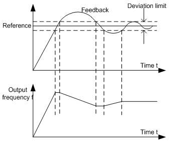
P09.08 | PID control deviation limit | 0.0–100.0% | 0.0–100.0 | 0.0% |
The output of PID system is relative to the maximum deviation of the close loop reference. As shown in the diagram below, PID adjuster stops regulating in the range of deviation limit. Set the function code properly to adjust the accuracy and stability of PID system.
Function code | Name | Description | Setting range | Default |
P09.09 | Upper limit of PID output | P09.10–100.0% (Max. frequency or voltage) | P09.10–100.0 | 100.0% |
P09.10 | Lower limit of PID output | -100.0%–P09.09 (Max. frequency or voltage) | -100.0–P09.09 | 0.0% |
The function code is used to set the upper and lower limit of PID adjuster output setting.
100.0% corresponds to the maximum output frequency (P00.03) or the maximum voltage (P04.31).
Function code | Name | Description | Setting range | Default |
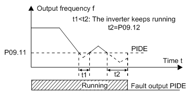
P09.11 | Feedback offline detection value | 0.0–100.0% | 0.0–100.0% | 0.0% |
P09.12 | Feedback offline detection time | 0.0–3600.0s | 0.0–3600.0 | 1.0s |
Set the PID feedback offline detection value. When the value is smaller than or equal to the feedback offline detection value and the duration exceeds the value set in P09.12, the VFD will alarm "PID feedback offline fault" and the keypad will display PIDE.
Function code | Name | Description | Setting range | Default |
P09.13 | PID adjustment | 0x0000–0x1111 LED ones: 0: Keep the integral adjustment when the frequency reaches the upper and lower limit 1: Stop the integral adjustment when the frequency reaches the upper and lower limit LED tens: 0: The same with the setting direction 1:Opposite to the setting direction LED hundreds: 0: Limit to the maximum frequency 1: Limit to frequency A LED thousands: 0:A+B frequency, the buffer of A frequency is invalid 1:A+B frequency, the buffer of A frequency is valid ACC/DEC is determined by ACC time 4 of P08.04 | 0000–1111 | 0x0001 |
LED ones:
0: Keep the integral adjustment when the frequency reaches the upper and lower limit: the integration responses the changes between the reference and feedback unless it reaches the internal integral limit. When the size between the reference and feedback changes, it needs more time to offset the impact of continuous working integration and the integration can change with the trend.
1: Stop the integral adjustment when the frequency reaches the upper and lower limit: if the integration keeps stable and the size between the reference and feedback changes, the integration will change along with the trend quickly.
Function code | Name | Description | Setting range | Default |
P09.14 | Proportional gain at low frequency (Kp) | 0.00–100.00 | 0.00–100.00 | 1.00 |
P09.15 | PID command of ACC/DEC time | 0.0–1000.0s | 0.0–1000.0s | 0.0s |
P09.16 | PID output filter time | 0.000–10.000s | 0.000–10.000s | 0.000s |
P10 Simple PLC and multi-step speed control group
Function code | Name | Description | Setting range | Default |
P10.00 | Simple PLC | 0: Stop after running once 1: Run at the final value after running once 2: Cycle running | 0–2 | 0 |
Set the simple PLC running mode.
0: Stop after running once: it is necessary to give the VFD the running command again after it finishes a single cycle and automatically stops.
1: Run at the final value after running once: the VFD automatically keeps the running frequency and direction of the last step after finishing a single cycle.
2: Cycle running: the VFD automatically enters into next cycle after finishing a single cycle and the system will not stop until there is a stop command.
Function code | Name | Description | Setting range | Default |
P10.01 | Simple PLC memory | 0: Power loss without memory 1: Power loss with memory | 0–1 | 0 |
Set simple PLC memory manners when power loss.
0: Power loss without memory
1: Power loss with memory: PLC will memorize the running step and frequency when power loss.
Function code | Name | Description | Setting range | Default |
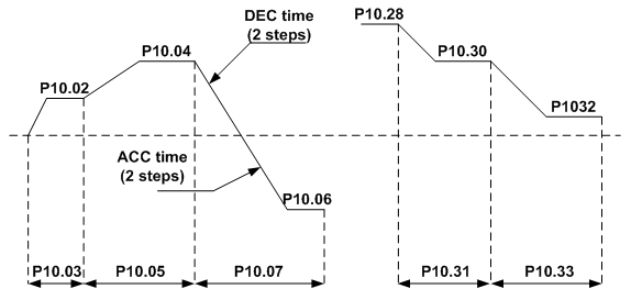
P10.02 | Multi-step speed 0 | -100.0–100.0% | -100.0–100.0 | 0.0% |
P10.03 | Running time of step 0 | 0.0–6553.5s(m) | 0.0–6553.5 | 0.0s |
P10.04 | Multi-step speed 1 | -100.0–100.0% | -100.0–100.0 | 0.0% |
P10.05 | Running time of step 1 | 0.0–6553.5s(m) | 0.0–6553.5 | 0.0s |
P10.06 | Multi-step speed 2 | -100.0–100.0% | -100.0–100.0 | 0.0% |
P10.07 | Running time of step 2 | 0.0–6553.5s(m) | 0.0–6553.5 | 0.0s |
P10.08 | Multi-step speed 3 | -100.0–100.0% | -100.0–100.0 | 0.0% |
P10.09 | Running time of step 3 | 0.0–6553.5s(m) | 0.0–6553.5 | 0.0s |
P10.10 | Multi-step speed 4 | -100.0–100.0% | -100.0–100.0 | 0.0% |
P10.11 | Running time of step 4 | 0.0–6553.5s(m) | 0.0–6553.5 | 0.0s |
P10.12 | Multi-step speed 5 | -100.0–100.0% | -100.0–100.0 | 0.0% |
P10.13 | Running time of step 5 | 0.0–6553.5s(m) | 0.0–6553.5 | 0.0s |
P10.14 | Multi-step speed 6 | -100.0–100.0% | -100.0–100.0 | 0.0% |
P10.15 | Running time of step 6 | 0.0–6553.5s(m) | 0.0–6553.5 | 0.0s |
P10.16 | Multi-step speed 7 | -100.0–100.0% | -100.0–100.0 | 0.0% |
P10.17 | Running time of step 7 | 0.0–6553.5s(m) | 0.0–6553.5 | 0.0s |
P10.18 | Multi-step speed 8 | -100.0–100.0% | -100.0–100.0 | 0.0% |
P10.19 | Running time of step 8 | 0.0–6553.5s(m) | 0.0–6553.5 | 0.0s |
P10.20 | Multi-step speed 9 | -100.0–100.0% | -100.0–100.0 | 0.0% |
P10.21 | Running time of step 9 | 0.0–6553.5s(m) | 0.0–6553.5 | 0.0s |
P10.22 | Multi-step speed 10 | -100.0–100.0% | -100.0–100.0 | 0.0% |
P10.23 | Running time of step 10 | 0.0–6553.5s(m) | 0.0–6553.5 | 0.0s |
P10.24 | Multi-step speed 11 | -100.0–100.0% | -100.0–100.0 | 0.0% |
P10.25 | Running time of step 11 | 0.0–6553.5s(m) | 0.0–6553.5 | 0.0s |
P10.26 | Multi-step speed 12 | -100.0–100.0% | -100.0–100.0 | 0.0% |
P10.27 | Running time of step 12 | 0.0–6553.5s(m) | 0.0–6553.5 | 0.0s |
P10.28 | Multi-step speed 13 | -100.0–100.0% | -100.0–100.0 | 0.0% |
P10.29 | Running time of step 13 | 0.0–6553.5s(m) | 0.0–6553.5 | 0.0s |
P10.30 | Multi-step speed 14 | -100.0–100.0% | -100.0–100.0 | 0.0% |
P10.31 | Running time of step 14 | 0.0–6553.5s(m) | 0.0–6553.5 | 0.0s |
P10.32 | Multi-step speed 15 | -100.0–100.0% | -100.0–100.0 | 0.0% |
P10.33 | Running time of step 15 | 0.0–6553.5s(m) | 0.0–6553.5 | 0.0s |
100% of the frequency setting corresponds to the maximum output frequency P00.03.
It is necessary for simple PLC to set P10.02–P10.33 to ensure the running frequency and direction of each step.
Note: The sign of multi-step speed decides the running direction of simple PLC. Value with minus indicates reverse running.
Multi-step speed can be set continuously in the range of -fmax–fmax
Goodrive300-29 VFDs can be set with 16-step speed selected by the combined codes of 1–4 multi-step terminals, corresponding to multi-step speed 0–15 separately.
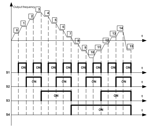
When S1=S2=S3=S4=OFF, the output way of the frequency is selected by the function code P00.06 or P00.07. When not all S1=S2=S3=S4 terminals are off, the VFD runs at multi-step speed and the multi-step speed has the priority over the keypad, analog values, high-speed pulse, PLC and communication frequency input. Select at most 16-step speed via the combined codes of S1, S2, S3 and S4.
The start-up and stop of multi-step speed is determined by the function code P00.01. The relationship between the terminals of S1, S2, S3 and S4 and the multi-step speed is shown as follows:
S1 | OFF | ON | OFF | ON | OFF | ON | OFF | ON | OFF | ON | OFF | ON | OFF | ON | OFF | ON |
S2 | OFF | OFF | ON | ON | OFF | OFF | ON | ON | OFF | OFF | ON | ON | OFF | OFF | ON | ON |
S3 | OFF | OFF | OFF | OFF | ON | ON | ON | ON | OFF | OFF | OFF | OFF | ON | ON | ON | ON |
S4 | OFF | OFF | OFF | OFF | OFF | OFF | OFF | OFF | ON | ON | ON | ON | ON | ON | ON | ON |
Step | 0 | 1 | 2 | 3 | 4 | 5 | 6 | 7 | 8 | 9 | 10 | 11 | 12 | 13 | 14 | 15 |
Function code | Name | Description | Setting range | Default |
P10.34 | Simple PLC 0–7 step ACC/DEC time | 0x0000–0xFFFF | 00000–FFFF | 0x0000 |
P10.35 | Simple PLC 8–15 step ACC/DEC time | 0x0000–0xFFFF | 00000–FFFF | 0x0000 |
Function code | Binary bit | Step | ACC/DEC time 1 | ACC/DEC time 2 | ACC/DEC time 3 | ACC/DEC time 4 | |
P10.34 | BIT1 | BIT0 | 0 | 00 | 01 | 10 | 11 |
BIT3 | BIT2 | 1 | 00 | 01 | 10 | 11 | |
BIT5 | BIT4 | 2 | 00 | 01 | 10 | 11 | |
BIT7 | BIT6 | 3 | 00 | 01 | 10 | 11 | |
BIT9 | BIT8 | 4 | 00 | 01 | 10 | 11 | |
BIT11 | BIT10 | 5 | 00 | 01 | 10 | 11 | |
BIT13 | BIT12 | 6 | 00 | 01 | 10 | 11 | |
BIT15 | BIT14 | 7 | 00 | 01 | 10 | 11 | |
P10.35 | BIT1 | BIT0 | 8 | 00 | 01 | 10 | 11 |
BIT3 | BIT2 | 9 | 00 | 01 | 10 | 11 | |
BIT5 | BIT4 | 10 | 00 | 01 | 10 | 11 | |
BIT7 | BIT6 | 11 | 00 | 01 | 10 | 11 | |
BIT9 | BIT8 | 12 | 00 | 01 | 10 | 11 | |
BIT11 | BIT10 | 13 | 00 | 01 | 10 | 11 | |
BIT13 | BIT12 | 14 | 00 | 01 | 10 | 11 | |
BIT15 | BIT14 | 15 | 00 | 01 | 10 | 11 | |
See the detailed instruction in following table:
After selecting corresponding ACC/DEC time, users have to convert the combined 16 binary bit into the decimal bit and set the related function codes.
Function code | Name | Description | Setting range | Default |
P10.36 | PLC restart | 0: Restart from the first step 1: Continue to run from the stop frequency | 0–1 | 0 |
Set the restart manners of PLC.
0: Restart from the first step: the VFD will restart from the first step after stop (caused by the stop command, faults or power loss).
1: Continue to run from the stop frequency: the VFD will record the running time at current step after stop (caused by the stop command or faults), automatically enter into the step and then remain to run at the frequency defined by the step.
Function code | Name | Description | Setting range | Default |
P10.37 | Multi-step time unit | 0: Second 1: Minute | 0–1 | 0 |
Set the time unit.
0: Second: the running time of all steps is counted by second.
1: Minute: the running time of all steps is counted by minute.
P11 Protective parameter group
Function code | Name | Description | Setting range | Default |
P11.00 | Phase loss protection | 0x00–0x11 LED ones: 0: Disable input phase loss protection 1: Enable input phase loss protection LED tens: 0: Disable output phase loss protection 1: Enable output phase loss protection | 00–11 | 11 |
Enable the function of phase loss protection.
Function code | Name | Description | Setting range | Default |
P11.01 | Instantaneous power loss frequency decreasing | 0: Disabled 1: Enabled | 0–1 | 0 |
Enable instantaneous power loss frequency-decreasing function.
Function code | Name | Description | Setting range | Default |
P11.02 | Frequency decreasing velocity of instantaneous power loss | 0.00Hz/s–P00.03Hz/s(Max. frequency) | 0.00Hz–P00.03 | 10.00Hz/s |
After the power loss of the grid, when the bus voltage drops to the instantaneous power loss frequency-decreasing point, the VFD begins to decrease the running frequency according to the decreasing velocity and make the motor in power generation again. The feedback power can maintain the bus voltage to ensure the continuous running of the VFD until the recovery of power.
Voltage degree | 660V |
Frequency-decreasing point of instantaneous power loss | 800V |
Note:
1. Adjusting the parameter properly can prevent the stop caused by the VFD protection during shifting the grid.
2. The function can be enabled only by disabling input phase loss protection.
Function code | Name | Description | Setting range | Default |
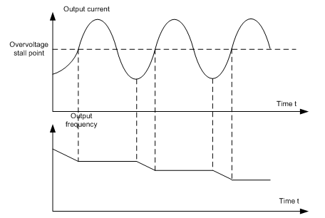
P11.03 | Overvoltage speed loss protection | 0: Disabled 1: Enabled | 0–1 | 1 |
Enable the function of overvoltage speed loss protection.
Note: For four-quadrant, set P11.03=0.
Function code | Name | Description | Setting range | Default |
P11.04 | Voltage protection of overvoltage stall | 120–150%(standard bus voltage) | 120–150% | 120% |
Set the protection point of overvoltage stall.
Function code | Name | Description | Setting range | Default |
P11.05 | Current limit action | Ones: current limit: 0:Invalid 1:Valid Tens: overload alarm of hardware current limit (for factory commissioning) 0: Valid 1: Invalid | 00–11 | 01 |
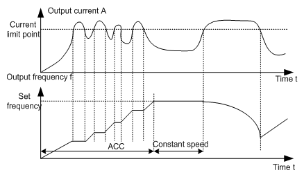
P11.06 | Automatic current limit level | 50.0–200.0% (100% corresponds to rated current) | 50.0–200.0 | 160.0% |
P11.07 | Frequency decreasing velocity during current limit | 0.00–50.00Hz/s | 0.00–50.00 | 10.00Hz/s |
During ACC running of the VFD, due to heavy load, the actual increasing ratio of the motor speed is lower than the increasing ratio of output frequency. The trips of the VFD will be caused by the ACC overcurrent fault if there are not any measures.
During the running of the VFD, this function will detect the output current and compare it with the limit level defined in P11.06. If it exceeds the level, the VFD will run at stable frequency during ACC running, while the VFD will derate to run during the constant running. If it exceeds the level continuously, the output frequency will keep decreasing to the lower limit. If the detected output current is lower than the limit level, the VFD will continue ACC running.
Function code | Name | Description | Setting range | Default |
P11.08 | VFD/Motor underload and overload pre-alarm | 0x000–0x131 LED ones: 0: Motor underload and overload pre-alarm, relative to motor rated current 1: VFD underload and overload pre-alarm, relative to VFD rated current LED tens: 0: VFD continues running after underload and overload pre-alarm 1: VFD continues running after underload pre-alarm and stop running after overload fault 2: VFD continues running after overload pre-alarm and stop running after underload fault 3: VFD stops running after underload and overload alarm LED hundreds: 0: Detect all the time 1: Detect in constant running | 000–131 | 0x000 |
P11.09 | Detection level of overload pre-alarm | P11.11–200% | P11.11–200 | 150% |
P11.10 | Detection time of overload pre-alarm | 0.1–3600.0s | 0.1–3600.0 | 1.0s |
P11.11 | Detection level of underload pre-alarm | 0%–P11.09 | 0–P11.09 | 50% |
P11.12 | Detection time of underload pre-alarm | 0.1–3600.0s | 0.1–3600.0 | 1.0s |
Overload pre-alarm signals will be output when the output current of the VFD or motor is higher than the detection level of overload pre-alarm (P11.09) and the duration exceeds the detection time of overload pre-alarm (P11.10).
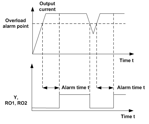
Underload pre-alarm signals will be output when the output current of the VFD or motor is lower than the detection level of underload pre-alarm (P11.11) and the duration exceeds the detection time of underload pre-alarm (P11.12).
Note: The set value of underload pre-alarm detection level (P11.11) should be smaller than the set value of overload pre-alarm detection level (P11.09).
Function code | Name | Description | Setting range | Default |
P11.13 | Output terminal action during undervoltage and auto-reset | 0x00–0x11 LED ones: 0: Action at undervoltage 1: No action at undervoltage LED tens: 0: Action during auto-reset 1: No action during auto-reset | 00–11 | 0x00 |
Select the action of fault output terminals on undervoltage and fault reset.
Function code | Name | Description | Setting range | Default |
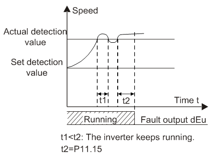
P11.14 | Detection value of speed deviation | 0.0–50.0% | 0.0–50.0 | 10.0% |
P11.15 | Detection time of speed deviation | 0.0–10.0s (No speed deviation protection at 0.0) | 0.0–10.0 | 0.5s |
Set the detection time of speed deviation.
Function code | Name | Description | Setting range | Default |
P11.16 | Automatic frequency-decreasing at voltage drop | 0: Invalid 1: Valid | 0–1 | 0 |
0: Invalid
1: Valid. When the grid voltage drops to the rated voltage, the VFD ensures output rated torque by automatic frequency decrease.
P12 Motor 2 parameter group
Function code | Name | Description | Setting range | Default |
P12.00 | Motor 2 type | 0: AM; 1: SM | 0–1 | 0 |
P12.01 | Asynchronous motor 2 rated power | 0.1–3000.0kW | 0.1–3000.0 | Depends on model |
P12.02 | Asynchronous motor 2 rated frequency | 0.01Hz–P00.03(Max. frequency) | 0.01–P00.03 | 50.00Hz |
P12.03 | Asynchronous motor 2 rated speed | 1–36000rpm | 1–36000 | Depends on model |
P12.04 | Asynchronous motor 2 rated voltage | 0–4000V | 0–4000 | Depends on model |
P12.05 | Asynchronous motor 2 rated current | 0.8–6000.0A | 0.8–6000.0 | Depends on model |
P12.06 | Asynchronous motor 2 stator resistor | 0.001–65.535Ω | 0.001–65.535Ω | Depends on model |
P12.07 | Asynchronous motor 2 rotor resistor | 0.001–65.535Ω | 0.001–65.535Ω | Depends on model |
P12.08 | Asynchronous motor 2 leakage inductance | 0.1–6553.5mH | 0.1–6553.5mH | Depends on model |
P12.09 | Asynchronous motor 2 mutual inductance | 0.1–6553.5mH | 0.1–6553.5mH | Depends on model |
P12.10 | Asynchronous motor 2 non-load current | 0.1–6553.5A | 0.1–6553.5A | Depends on model |
P12.11 | Magnetic saturation coefficient 1 for the iron core of AM 2 | 0.0–100.0% | 0.0–100.0 | 80.0% |
P12.12 | Magnetic saturation coefficient 2 for the iron core of AM 2 | 0.0–100.0% | 0.0–100.0 | 68.0% |
P12.13 | Magnetic saturation coefficient 3 for the iron core of AM 2 | 0.0–100.0% | 0.0–100.0 | 57.0% |
P12.14 | Magnetic saturation coefficient 4 for the iron core of AM 2 | 0.0–100.0% | 0.0–100.0 | 40.0% |
P12.15 | Rated power of synchronous motor 2 | 0.1–3000.0kW | 0.1–3000.0 | Depends on model |
P12.16 | Rated frequency of synchronous motor 2 | 0.01Hz–P00.03(Max. frequency) | 0.01–P00.03 | 50.00Hz |
P12.17 | Number of poles pairs for synchronous motor 2 | 1–50 | 1–50 | 2 |
P12.18 | Rated voltage of synchronous motor 2 | 0–1200V | 0–1200 | Depends on model |
P12.19 | Rated current of synchronous motor 2 | 0.8–6000.0A | 0.8–6000.0 | Depends on model |
P12.20 | Stator resistor of synchronous motor 2 | 0.001–65.535Ω | 0.001–65.535 | Depends on model |
P12.21 | Direct axis inductance of synchronous motor 2 | 0.01–655.35mH | 0.01–655.35 | Depends on model |
P12.22 | Quadrature axis inductance of synchronous motor 2 | 0.01–655.35mH | 0.01–655.35 | Depends on model |
P12.23 | Back EMF constant of synchronous motor 2 | 0–10000V | 0–10000 | 300 |
P12.24 | Initial pole position of synchronous motor 2 (reserved) | 0–FFFFH | 0–FFFFH | 0x0000 |
P12.25 | Identification current of synchronous motor 2 (reserved) | 0%–50%(Motor rated current) | 0–50 | 10% |
P12.26 | Motor 2 overload protection | 0:No protection 1:Common motor(with low speed compensation) 2:Variable frequency motor(without low speed compensation) | 0–2 | 2 |
P12.27 | Motor 2 overload protection coefficient | 20.0%–120.0% | 20.0–120.0 | 100.0% |
P12.28 | Correction coefficient of motor 2 power | 0.00–3.00 | 0.00–3.00 | 1.00 |
P12.29 | Parameter display of motor 2 | 0: Display according to the motor type 1: Display all parameters | 0–1 | 0 |
For the parameter settings of motor 2, refer to the settings of motor 1 in P02 group.
P13 Synchronous motor control parameter group
Function code | Name | Description | Setting range | Default |
P13.00 | Reduction coefficient of source current | 0.0%–100.0%(Motor rated current) | 0.0–100.0 | 80.0% |
Set the reduction coefficient of source current for the VFD.
Function code | Name | Description | Setting range | Default |
P13.01 | Original pole test mode | 0: No test 1: High-frequency superposition (Reserved) 2: Pulse superposition (Reserved) | 0–2 | 0 |
Set the test mode of the original pole of the VFD.
Function code | Name | Description | Setting range | Default |
P13.02 | Source current 1 | 0.0%–100.0%(Motor rated current) | 0.0–100.0 | 20.0% |
Source current is the positioning current of the magnetic pole position. Source current 1 is valid under the frequency point of current shifting. Increasing the value can raise the starting torque.
Function code | Name | Description | Setting range | Default |
P13.03 | Source current 2 | 0.0%–100.0%(Motor rated current) | 0.0–100.0 | 10.0% |
Source current is directional current of the magnetic pole position. Source current 2 is valid under the frequency point of current shifting. There is no need to modify the value generally.
Function code | Name | Description | Setting range | Default |
P13.04 | Shift frequency of source current | 0.00Hz–P00.03(Max. frequency) | 0.00–P00.03 | 10.0Hz |
It is the valid frequency shifting point between source current 1 and current 2.
Function code | Name | Description | Setting range | Default |
P13.05 | High-frequency superposing frequency (Reserved) | 200Hz–1000Hz | 200–1000 | 500Hz |
P13.06 | Pulse superposing voltage | 0.0–300.0%(Motor rated voltage) | 0.0–300.0 | 40.0% |
P13.06 is the pulse voltage when P13.01 is set to 2.
Function code | Name | Description | Setting range | Default |
P13.08 | Control parameter 1 | 0–65535 | 0–65535 | 0 |
P13.09 | Control parameter 2 | 0–655.35 | 0–655.35 | 2.00 |
Function code | Name | Description | Setting range | Default |
P13.11 | Maladjustment detection time | 0.0–10.0s | 0.0–10.0 | 0.5s |
Adjust the response of anti-maladjustment. Bigger load inertia may increase the value, but the response will be slower.
Function code | Name | Description | Setting range | Default |
P13.12 | High frequency compensation coefficient | 0–100.0% | 0–100.0 | 0.0% |
When the motor speed is faster than the rated speed, the parameter is valid, if vibration occurs to the motor, please adjust the parameter.
Function code | Name | Description | Setting range | Default |
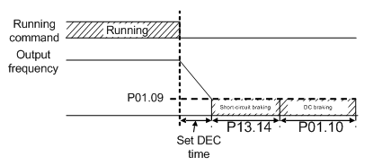
P13.13 | Braking current of short-circuit | 0.0–150.0%(VFD) | 0.0–150.0 | 0.0% |
P13.14 | Braking retention time before starting | 0.0–50.00s | 0.0–50.00 | 0.00s |
P13.15 | Braking retention time when stopping | 0.0–50.00s | 0.0–50.00 | 0.00s |
When the VFD is starting and startup mode is direct startup (P01.00=0), set P13.14 to a non-zero value to enter short circuit braking.
When the running frequency is lower than P01.09 during the stopping of the VFD, set 13.15 to a non-zero value to enter into stopping short circuited braking and then carry out the DC braking at the time set by P01.12
P14 Serial communication group
Function code | Name | Description | Setting range | Default |
P14.00 | Local communication address | 1–247, 0 is broadcast communication address | 1–247 | 0 |
When the master is at write frame and the communication address of the slave is set to 0 (broadcast communication address), all the slaves of the Modbus will accept the frame without response.
Local communication address is unique in communication network and it is the foundation to achieve point-to-point communication between the upper machine and VFD.
Note: The address of the slave cannot be set to 0.
Function code | Name | Description | Setting range | Default |
P14.01 | Communication baud rate | 0: 1200BPS 1: 2400BPS 2: 4800BPS 3: 9600BPS 4: 19200BPS 5: 38400BPS 6: 57600BPS | 0–6 | 3 |
Set the data baud rate between the upper computer and VFD.
Note: The baud rates set by the upper machine and VFD should agree with each other; otherwise, the communication is disabled. The larger the baud rate is, the faster the communication is.
Function code | Name | Description | Setting range | Default |
P14.02 | Data bit checkout | 0: No check (N, 8, 1) for RTU 1: Even check (E, 8, 1) for RTU 2: Odd check (O, 8, 1) for RTU 3: No check (N, 8, 2) for RTU 4: Even check (E, 8, 2) for RTU 5: Odd check (O, 8, 2) for RTU | 0–5 | 0 |
The upper machine and VFD must be the same in data format. Otherwise, communication fails.
Function code | Name | Description | Setting range | Default |
P14.03 | Communication response delay | 0–200ms | 0–200 | 5 |
The function code refers to the interval when the VFD receives data and sends response to the upper machine. If the response delay is shorter than the processing time, take the processing time as the standard. If the response delay is longer than the processing time, delay and wait to send data to the upper computer until the response delay arrival after the system finishes processing data.
Function code | Name | Description | Setting range | Default |
P14.04 | Fault time of communication timeout | 0.0(Invalid),0.1–60.0s | 0.0–60.0 | 0.0s |
When the function code is set to 0.0, the parameter will be invalid.
When the function code is set to non-zero and the interval between the current and next communication exceeds the communication timeout, the system will alarm 485 communication fault (CE).
Generally, set the parameter to be invalid. The parameter setting can monitor communication state in continuous communication system.
Function code | Name | Description | Setting range | Default |
P14.05 | Transmission fault processing | 0: Alarm and coast to stop 1: Continue to run without alarm 2: Stop according to stop way without alarm (only in communication control mode) 3: Stop according to stop way without alarm (in all control modes) | 0–3 | 0 |
Set the processing ways for transmission fault.
Function code | Name | Description | Setting range | Default |
P14.06 | Communication processing action | LED ones: 0: With response to write operation 1: Without response to write operation LED tens: 0: Communication encryption setting is invalid 1: Communication encryption setting is valid | 00–11 | 0x00 |
Select communication processing actions.
LED ones:
0: With response to write operation: there are responses to write and read commands of the upper computer.
1: Without response to write operation: there is response only to read command and no response to the write command, which can improve the communication efficiency.
Note: For details about Modbus, see Appendix B.
P15 PROFIBUS function group
Function code | Name | Description | Setting range | Default |
P15.00 | Module type | 0: PROFIBUS 1: CANopen | 0–1 | 0 |
Select the communication protocol.
Function code | Name | Description | Setting range | Default |
P15.01 | PROFIBUS/CANopen module address | 0–127 | 0–127 | 2 |
The function code is used to identify the address of the VFD during serial communication.
Note: 0 is the broadcast address only for receiving and carrying out broadcast command of upper machine rather than response. The function code setting change takes effect only after the VFD is powered off and restarted.
Function code | Name | Description | Setting range | Default |
P15.02 | PZD2 receiving | 0: Invalid 1: Set frequency 2: PID reference 3: PID feedback 4: Torque set value 5: Set value of forward rotation upper-limit frequency 6: Set value of reverse rotation upper-limit frequency 7: Electromotion torque upper limit 8: Braking torque upper limit 9: Virtual input terminal command 10: Virtual output terminal command 11: Voltage set value (special for V/F separation) 12: AO output set value 1 13: AO output set value 2 | 0–20 | 0 |
P15.03 | PZD3 receiving | 0–20 | 0 | |
P15.04 | PZD4 receiving | 0–20 | 0 | |
P15.05 | PZD5 receiving | 0–20 | 0 | |
P15.06 | PZD6 receiving | 0–20 | 0 | |
P15.07 | PZD7 receiving | 0–20 | 0 | |
P15.08 | PZD8 receiving | 0–20 | 0 | |
P15.09 | PZD9 receiving | 0–20 | 0 | |
P15.10 | PZD10 receiving | 0–20 | 0 | |
P15.11 | PZD11 receiving | 0–20 | 0 | |
P15.12 | PZD12 receiving | 0–20 | 0 |
For the second PZD in PROFIBUS-DP communication and master communication (receiving), see detailed information as follows:
Function code | Name | Description |
0 | Invalid | |
1 | Set frequency | 0–Fmax (Unit: 0.01Hz) |
2 | PID reference | Range (0–1000, 1000 corresponds to 100.0%) |
3 | PID feedback | Range (0–1000, 1000 corresponds to 100.0%) |
4 | Torque set value | Range (-3000–3000, 1000 corresponds to 100.0% of motor rated current) |
5 | Set value of forward rotation upper-limit frequency | 0–Fmax (Unit: 0.01Hz) |
6 | Set value of reverse rotation upper-limit frequency | 0–Fmax (Unit: 0.01Hz) |
7 | Electromotion torque upper limit | 0–3000, 1000 corresponds to 100.0% of motor rated current |
8 | Braking torque upper limit | 0–2000, 1000 corresponds to 100.0% of motor rated current |
9 | Virtual input terminal command | Range: 0x000–0x1FF |
10 | Virtual output terminal command | Range: 0x00–0x0F |
11 | Voltage set value | Special for V/F separation, range (0–1000, 1000 corresponds to 100.0% of motor rated voltage) |
12 | AO output set value 1 | Range (-1000–1000, 1000 corresponds to 100.0%) |
13 | AO output set value 2 | Range (-1000–1000, 1000 corresponds to 100.0%) |
Function code | Name | Description | Setting range | Default |
P15.13 | PZD2 sending | 0: Invalid 1: Running frequency 2: Set frequency 3: Bus voltage 4: Output voltage 5: Output current 6: Output torque actual value 7: Output power actual value 8: Running rotating speed 9: Running linear speed 10: Ramp reference frequency 11: Fault code 12: AI1 value 13: AI2 value 14: AI3 value 15: PULSE frequency 16: Input state of terminals 17: Output state of terminals 18: PID reference 19: PID feedback 20: Motor rated torque 21: Control word | 0–20 | 0 |
P15.14 | PZD3 sending | 0–21 | 0 | |
P15.15 | PZD4 sending | 0–21 | 0 | |
P15.16 | PZD5 sending | 0–21 | 0 | |
P15.17 | PZD6 sending | 0–21 | 0 | |
P15.18 | PZD7 sending | 0–21 | 0 | |
P15.19 | PZD8 sending | 0–21 | 0 | |
P15.20 | PZD9 sending | 0–21 | 0 | |
P15.21 | PZD10 sending | 0–21 | 0 | |
P15.22 | PZD11 sending | 0–21 | 0 | |
P15.23 | PZD12 sending | 0–21 | 0 |
For the second PZD in PROFIBUS-DP communication and master communication (sending), see detailed information as follows:
Function code | Name | Description |
0 | Invalid | |
1 | Running frequency | (*100,Hz) |
2 | Set frequency | (*100,Hz) |
3 | Bus voltage | (*10,V) |
4 | Output voltage | (*1,V) |
5 | Output current | (*10,A) |
6 | Output torque actual value | (*10,%) |
7 | Output power actual value | (*10,%) |
8 | Running rotating speed | (*1,RPM) |
9 | Running linear speed | (*1,m/s) |
10 | Ramp reference frequency | |
11 | fault code | |
12 | AI1 value | (*100,V) |
13 | AI2 value | (*100,V) |
14 | AI3 value | (*100,V) |
15 | PULSE frequency | (*100,kHz) |
16 | Input state of terminals | |
17 | Output state of terminals | |
18 | PID reference | (*100,%) |
19 | PID feedback | (*100,%) |
20 | Motor rated torque | |
21 | Control word |
Function code | Name | Description | Setting range | Default |
P15.24 | Temporary variable 1 for PZD sending | 0–65535 | 0–65535 | 0 |
The function code is use as the temporary variable when PZD sends data.
The function code P15.24 is enabled to write at any state.
Function code | Name | Description | Setting range | Default |
P15.25 | Fault time of DP communication overtime | 0.0: Invalid 0.1–60.0s | 0.0–60.0 | 0.0s |
When the function code is set to 0.0s, the fault time of communication timeout will be invalid.
When the function code is set to non-zero (actual value, unit: second) and the interval between the current and next communication exceeds the communication timeout, the system will alarm DP communication fault (E-dP).
Function code | Name | Description | Setting range | Default |
P15.26 | Fault time of CANopen communication timeout | 0.0: Invalid 0.1–60.0s | 0.0–60.0 | 0.0 |
When the function code=0.0s, the communication timeout fault will be invalid.
When the function code=non-zero and the interval between the current and next communication exceeds the communication timeout, the system will alarm communication fault (E-CAN). Generally, set the parameter to be invalid. The parameter setting can monitor the state in continuous communication system.
Function code | Name | Description | Setting range | Default |
P15.27 | CANopen baud rate | 0: 1000k 1: 800k 2: 500k 3: 250k 4: 125k 5: 100k 6: 50k 7: 20k Note:The function code setting change takes effect only after the VFD is powered off and restarted. | 0–7 | 0 |
P16 Ethernet function group
Function code | Name | Description | Setting range | Default |
P16.00 | Ethernet communication speed setting | 0: Self-adapting 1: 100M full-duplex 2: 100M half-duplex 3: 10M full-duplex 4: 10M half-duplex | 0–4 | 3 |
The function code is used for Ethernet communication speed setting. Generally, select the default value.
Note: The function code setting change takes effect only after the VFD is powered off and restarted.
Function code | Name | Description | Setting range | Default |
P16.01 | IP address 1 | 0–255 | 0–255 | 192 |
P16.02 | IP address 2 | 0–255 | 0–255 | 168 |
P16.03 | IP address 3 | 0–255 | 0–255 | 0 |
P16.04 | IP address 4 | 0–255 | 0–255 | 1 |
P16.05 | Subnet mask 1 | 0–255 | 0–255 | 255 |
P16.06 | Subnet mask 2 | 0–255 | 0–255 | 255 |
P16.07 | Subnet mask 3 | 0–255 | 0–255 | 255 |
P16.08 | Subnet mask 4 | 0–255 | 0–255 | 0 |
The function codes are used to set the IP addresses and subnet masks for Ethernet communication.
IP address format: P16.01. P16.02. P16.03. P16.04
For example: IP address is 192.168.0.1.
Subnet mask format: P16.05. P16.06. P16.07. P16.08
For example: Subnet mask is 255.255.255.0.
Note: The function code setting change takes effect only after the VFD is powered off and restarted.
Function code | Name | Description | Setting range | Default |
P16.09 | Gateway 1 | 0–255 | 0–255 | 192 |
P16.10 | Gateway 2 | 0–255 | 0–255 | 168 |
P16.11 | Gateway 3 | 0–255 | 0–255 | 1 |
P16.12 | Gateway 4 | 0–255 | 0–255 | 1 |
Set the gateway for Ethernet communication.
P17 State view function group
Function code | Name | Description | Setting range | Default |
P17.00 | Set frequency | Display current set frequency of the VFD Range: 0.00Hz–P00.03 | 0.00–P00.03 | 0.00Hz |
P17.01 | Output frequency | Display current output frequency of the VFD Range: 0.00Hz–P00.03 | 0.00–P00.03 | 0.00Hz |
P17.02 | Ramp reference frequency | Display current ramp given frequency of the VFD Range: 0.00Hz–P00.03 | 0.00–P00.03 | 0.00Hz |
P17.03 | Output voltage | Display current output voltage of the VFD Range: 0–4000V | 0–4000 | 0V |
P17.04 | Output current | Display current output current of the VFD Range: 0.0–3000.0A | 0.0–3000.0 | 0.0A |
P17.05 | Motor speed | Display the rotation speed of the motor. Range: 0–65535RPM | 0–65535 | 0 RPM |
P17.06 | Torque current | Display current torque current of the VFD Range: -3000.0–3000.0A | -3000.0–3000.0A | 0.0A |
P17.07 | Exciting current | Display current exciting current of the VFD Range: -3000.0–3000.0A | -3000.0–3000.0A | 0.0A |
P17.08 | Motor power | Display current power of the motor. Setting range: -300.0%–300.0% (the rated current of the motor) | -300.0–300.0 | 0.0% |
P17.09 | Output torque | Display the current output torque of the VFD. Range: -250.0–250.0% | -250.0–250.0 | 0.0% |
P17.10 | Evaluated motor frequency | Evaluate the motor rotor frequency on open loop vector Range: 0.00– P00.03 | 0.00–P00.03 | 0.00Hz |
P17.11 | DC bus voltage | Display current DC bus voltage of the VFD Range: 0.0–6000.0V | 0.0–6000.0 | 0V |
P17.12 | Digital input terminals state | Display current switch input terminals state of the VFD 0000–00FF | 0000–00FF | 0 |
P17.13 | Digital output terminals state | Display current switch output terminals state of the VFD 0000–000F | 0000–000F | 0 |
P17.14 | Digital adjustment | Display the adjustment through the keypad of the VFD. Range : 0.00Hz–P00.03 | 0.00Hz–P00.03 | 0.00Hz |
P17.15 | Torque reference | Display the torque given, the percentage to the current rated torque of the motor. Setting range: -300.0%–300.0% (the rated current of the motor) | -300.0–300.0 | 0.0% |
P17.19 | AI1 input voltage | Display analog AI1 input signal Range: 0.00–10.00V | 0.00–10.00 | 0.00V |
P17.20 | AI2 input voltage | Display analog AI2 input signal Range: -10.00–10.00V | -10.00–10.00 | 0.00V |
P17.21 | AI3 input voltage | Display analog AI3 input signal Range: 0.00–10.00V | 0.00–10.00 | 0.00V |
P17.22 | HDI input frequency | Display HDI input frequency Range: 0.00–50.00kHz | 0.00–50.00 | 0.00 kHz |
P17.23 | PID reference | Display PID given value Range: -100.0–100.0% | -100.0–100.0 | 0.0% |
P17.24 | PID feedback | Display PID response value Range: -100.0–100.0% | -100.0–100.0 | 0.0% |
P17.25 | Power factor of the motor | Display the current power factor of the motor. Range: -1.00–1.00 | -1.00–1.00 | 0.0 |
P17.26 | Current running time | Display the current running time of the VFD. Range:0–65535m | 0–65535 | 0min |
P17.27 | Simple PLC and the current step of the multi-step speed | Display simple PLC and the current stage of the multi-step speed Range: 0–15 | 0–15 | 0 |
P17.28 | ASR controller output | The percentage of the rated torque of the relative motor, display ASR controller output Range: -300.0%–300.0% (the rated current of the motor) | -300.0–300.0 | 0.0% |
P17.32 | Magnetic flux linkage | Display the magnetic flux linkage of the motor. Range: 0.0%–200.0% | 0.0–200.0 | 0.0% |
P17.33 | Exciting current reference | Display the exciting current reference in the vector control mode. Range: -3000.0–3000.0A | -3000.0–3000.0 | 0.0A |
P17.34 | Torque current reference | Display the torque current reference in the vector control mode. Range: -3000.0–3000.0A | -3000.0–3000.0 | 0.0A |
P17.35 | AC current | Display the value of inlet current in AC side. Range: 0.0–5000.0A | 0.0–5000.0 | 0.0A |
P17.36 | Output torque | Display the output torque. Positive value is in the electromotion state, and negative is in the power generating state. Range : -3000.0Nm–3000.0Nm | 0–65535 | 0.0Nm |
P17.37 | Count value of motor overload | 0–100(100 reports OL1 fault) | 0–100 | 0 |
P17.38 | PID output | -100.00–100.00% | -100.00–100.0 | 0.00% |
P17.39 | Wrong download of parameters | 0.00–99.99 | 0.00–99.99 | 0.00 |