The VFD layout is shown in the figure below (take a 015G/018P VFD as an example).
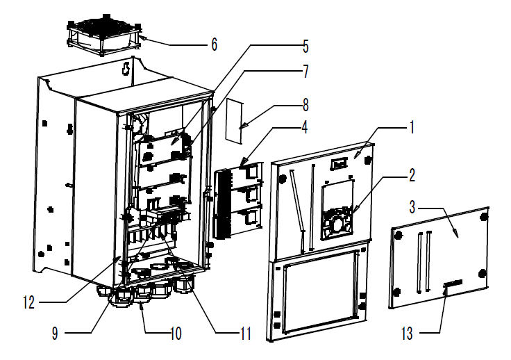
Figure 3–5 Structure diagram
No. | Name | Instruction |
1 | Upper cover | Protect internal components and parts |
2 | Keypad | For details, see section 5.4 "Keypad operation" |
3 | Lower cover | Protect internal components and parts |
4 | Extension card | Optional. For details, see Appendix A "Extension cards" |
5 | Baffle of control board | Protect the control board and install extension card |
6 | Cooling fan | For details, see chapter 8 "Routine maintenance" |
7 | Keypad interface | Connect the keypad |
8 | Nameplate | For details, see chapter 3 "Product overview" |
9 | Control terminals | For details, see chapter 4 "Installation guide" |
10 | Waterproof connector | Lock and secure connection cables |
11 | Main circuit terminal | For details, see chapter 4 "Installation guide" |
12 | POWER indicator | Power indicator |
13 | Label of GD350 IP54 product series | For details, see section 3.5 "Model code" of this chapter |