4.2.1 Installation environment
Installation environment is essential for the VFD to operate at its best in the long run. The installation environment of the VFD should meet the following requirements.
Environment | Condition |
Installation site | Indoors |
Ambient temperature |
|
Humidity |
|
Storage temperature | -30–+60°C |
Running environment | The installation site should meet the following requirements.
|
Altitude |
|
Vibration | The max. amplitude of vibration should not exceed 5.8m/s2 (0.6g) |
Installation direction | Install the VFD vertically to ensure good heat dissipation effect |
Note: GD350 IP54 series VFDs must be installed in ventilated environments free of corrosive gases and conductive dust.
4.2.2 Installation direction
The VFD can be installed on the wall or in a cabinet.
The VFD must be installed vertically. Check the installation position according to following requirements. See Appendix C "Dimension drawings" for detailed outline dimensions.
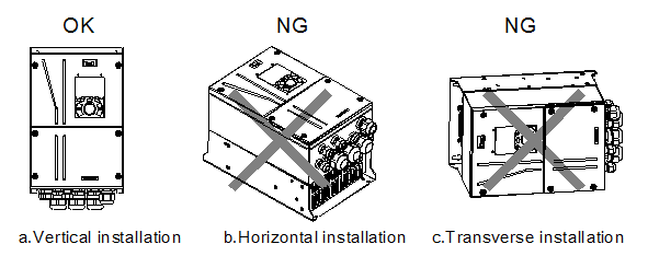
Figure 4–1 Installation direction of the VFD
4.2.3 Installation mode
The VFDs can be installed in two modes, depending on the different VFD dimensions:
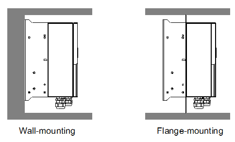
Figure 4–2 Installation mode
(1) Mark the position of the installation hole. See Appendix C "Dimension drawings" for the position of installation hole;
(2) Mount the screws or bolts onto the designated position;
(3) Put the VFD on the wall;
(4) Tighten the fixing screws on the wall.
Note: Flange-mounting plate is a must for 004G/5R5P-110G/132P VFDs that adopt flange-mounting mode.
4.2.4 Single-unit installation
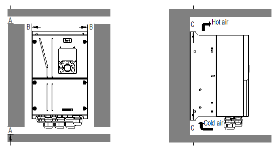
Figure 4–3 Single-unit installation
Note: The min. dimension of B and C is 100mm.
4.2.5 Multiple-unit installation
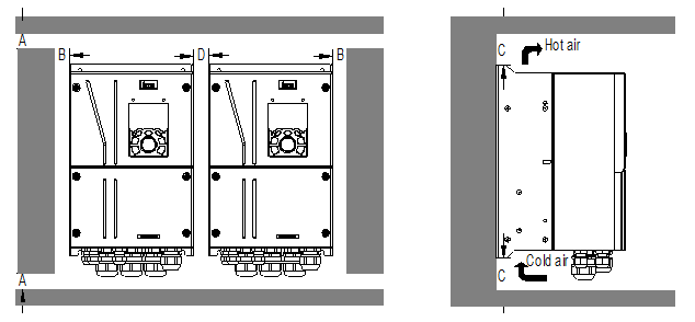
Figure 4–4 Parallel installation
Note:
1. When users install VFDs in different sizes, align the top of each VFD before installation for the convenience of future maintenance.
2. The min dimension of B and C is 100mm, and the dimention of D can be 0, that is zero-clearance parallel installation is supported.
4.2.6 Vertical installation
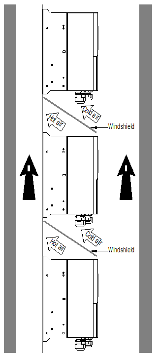
Figure 4–5 Vertical installation
Note: During vertical installation, users must install windshield, otherwise, the VFD will experience mutual interference, and the heat dissipation effect will be degraded.
4.2.7 Tilted installation
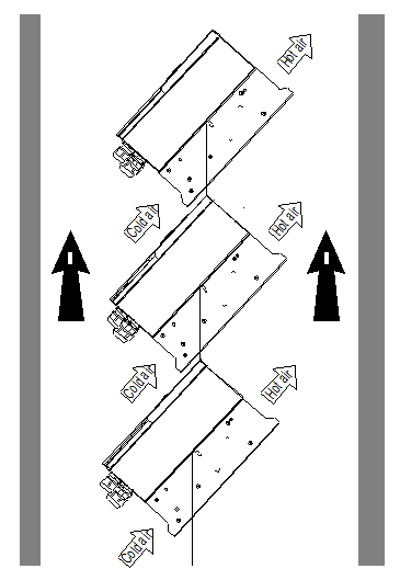
Figure 4–6 Tilted installation
Note: During tilted installation, it is a must to ensure the air inlet duct and air outlet duct are separated from each other to avoid mutual interference.