4.3.1 Wiring diagram of main circuit
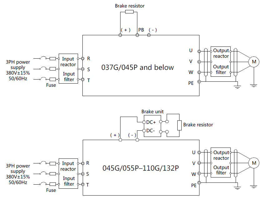
Figure 4–7 Main circuit wiring diagram
Note:
1. The fuse, DC reactor, brake unit, brake resistor, input reactor, input filter, output reactor and output filter are optional parts. See Appendix D "Optional peripheral accessories" for details.
2. When connecting the brake resistor, take off the yellow warning sign marked with PB, (+) and (-) on the terminal block before connecting the brake resistor wire, otherwise, poor contact may occur.
4.3.2 Main circuit terminal diagram
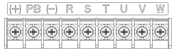
Figure 4–8 022G/030P and below
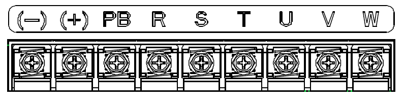
Figure 4–9 030G/037P–037G/045P
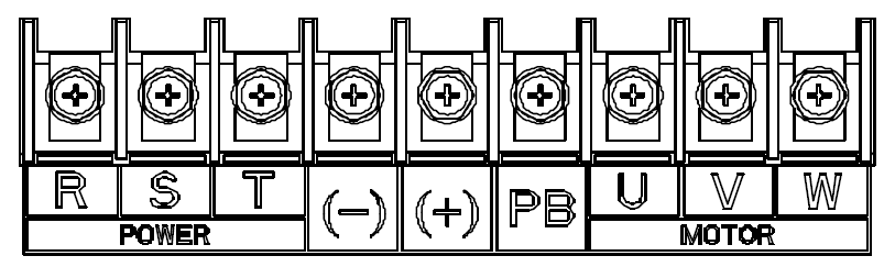
Figure 4–10 045G/055P–110G/132P (Enabling PB when a braking unit is embedded)
Terminal sign | Terminal name | Function description | |
037G/045P and below | 045G/055P–110G/132P | ||
R, S, T | Main circuit power input | 3PH AC input terminal, connect to the grid | |
U, V, W | VFD output | 3PH AC output terminal, connect to the motor | |
(+) | Brake resistor terminal 1 | Brake unit terminal 1 | (+) and (-) are connected with the terminals of brake unit. PB and (+) are connected with the terminals of brake resistor. |
(-) | / | Brake unit terminal 2 | |
PB | Brake resistor terminal 2 | None | |
PE | Grounding resistor is less than 10 ohm | Grounding terminal for safe protection; each machine must carry two PE terminals and proper grounding is required | |
Note:
1. Do not use asymmetrical motor cable. If there is a symmetrical grounding conductor in the motor cable besides the conductive shielded layer, ground the grounding conductor on the VFD end and motor end.
2. Brake resistor, brake unit and DC reactor are optional parts.
3. Route the motor cable, input power cable and control cables separately.
4. "None" means this terminal is not for external connection.
5. GD series VFDs cannot share the DC bus with CH series VFDs.
6. When sharing the DC bus, the VFDs must be the same in power and must be simultaneously powered on or off.
7. In shared DC bus running mode, current balance on the VFD input side must be considered during wiring, and equalizing reactors are recommended to be configured.
4.3.3 Wiring process of the main circuit terminals
1. Connect the grounding line of the input power cable to the grounding terminal (PE) of the VFD, and connect the 3PH input cable to R, S and T terminals and tighten up.
2. Connect the grounding line of the motor cable to the grounding terminal of the VFD, and connect 3PH motor cable to U, V and W terminals and tighten up.
3. Connect the brake resistor which carries cables to the designated position.
4. Fix all the cables outside the VFD mechanically if allowed.
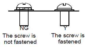
Figure 4–11 Screw installation diagram