LCD keypad is included in the standard configuration of GD350 IP54 series VFDs. Users can control the VFD start/stop, read state data and set parameters via keypad.
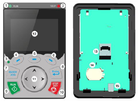
Figure 5–1 Keypad diagram
Note:
1. LCD keypad is armed with real-time clock, which can run properly after power off when installed with batteries. The clock battery (type: CR2032) should be purchased by the user separately.
2. LCD keypad support parameter-copy.
No. | Name | Instruction | |||
1 | State Indicator | (1) | RUN | Running indicator; LED off – the VFD is stopped; LED blinking – the VFD is in parameter autotune LED on – the VFD is running | |
2) | TRIP | Fault indicator; LED on – in fault state LED off – in normal state LED blinking – in pre-alarm state | |||
(3) | QUICK/JOG | Short-cut key indicator, which displays different state under different functions, see definition of QUICK/JOG key for details | |||
2 | Button area | (4) |
| Function key | The function of function key varies with the menu; The function of function key is displayed in the footer |
(5) |
| ||||
(6) |
| ||||
(7) |
| Short-cut key | Re-definable. It is defined as JOG function by default, namely jogging. The function of short-cut key can be set by the ones of P07.12, as shown below. 0: No function ; 1: Jogging (linkage indicator (3); logic: NO); 2: Reserved; 3: FWD/REV switch-over (linkage indicator (3); logic: NC) ; 4: Clear UP/DOWN setting (linkage indicator (3) logic: NC) ; 5: Coast to stop (linkage indicator (3); logic: NC) ; 6: Switching running command reference mode in order (linkage indicator (3); logic: NC) ; 7: Reserved; Note: After restoring to default values, the default function of short-cut key (7) is 1. | ||
(8) |
| Confirmation key | The function of confirmation key varies with menus, eg confirming parameter setup, confirming parameter selection, entering the next menu, etc. | ||
(9) |
| Running key | Under keypad operation mode, the running key is used for running operation or autotuning operation. | ||
(10) |
| Stop/ Reset key | During running state, press the Stop/Reset key can stop running or autotuning; this key is limited by P07.04. During fault alarm state, all the control modes can be reset by this key. | ||
(11) |
| Direction key UP: DOWN: LEFT: RIGHT: | UP: The function of UP key varies with interfaces, eg shifting up the displayed item, shifting up the selected item, changing digits, etc; DOWN: The function of DOWN key varies with interfaces, eg shifting down the displayed item, shifting down the selected item, changing digits, etc; LEFT: The function of LEFT key varies with interfaces, eg switch over the monitoring interface, eg shifting the cursor leftward, exiting current menu and returning to previous menu, etc; RIGHT: The function of RIGHT key varies with interfaces, eg switch over the monitoring interface, shifting the cursor rightward, enter the next menu etc. | ||
3 | Display area | (12) | LCD | Display screen | 240×160 dot-matrix LCD; display three monitoring parameters or six sub-menu items simultaneously |
4 | Others | (13) | RJ45 interface | RJ45 interface | RJ45 interface is used to connect to the VFD. |
(14) | Battery holder | Clock battery holder | The battery holder is used for replacing or installing a battery for the clock. | ||
(15) | USB terminal | mini USB terminal | Mini USB terminal is used to connect to the USB flash drive through an adapter. | ||


The LCD has different display areas, which displays different contents under different interfaces. The figure below is the main interface of stop state.
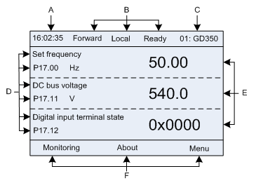
Figure 5–2 Main interface of LCD
Area | Name | Displayed contents |
Header A | Real-time display area | Display the real-time; clock battery is not included; the time needs to be reset when powering on the VFD |
Header B | VFD running state display area | Display the running state of the VFD: 1. Display motor rotating direction: "Forward" – Run forward during operation; Reverse – Run reversely during operation; "Forbid" – Reverse running is forbidden; 2. Display VFD running command channel: "Local" – Keypad; "Terminal"–Terminal; "Remote"–Communication 3. Display current running state of the VFD : "Ready" – The VFD is in stop state (no fault); "Run" – The VFD is in running state; "Jog"–The VFD is in jogging state; "Pre-alarm"–the VFD is under pre-alarm state during running; "Fault"–VFD fault occurred. |
Header C | VFD station no. and model display area | 1. Display VFD station no.: 01–99, applied in multi-drive applications (reserved function); 2. VFD model display: "GD350–current VFD is GD350 series VFD. |
Display D | The parameter name and function code monitored by the VFD | Display the parameter name and corresponding function code monitored by the VFD; three monitoring parameters can be displayed simultaneously. The monitoring parameter list can be edited by the user. |
Display E | Parameter value monitored by the VFD | Display the parameter value monitoring by the VFD, the monitoring value will be refreshed in real time. |
Footer F | Corresponding menu of function key (4), (5) and (6) | Corresponding menu of function key (4), (5) and (6). The corresponding menu of function key (4), (5) and (6) varies with interfaces, and the contents displayed in this area is also different. |