The display state of GD350 IP54 series keypad is divided into stop parameter display state, running parameter display stateand fault alarm display state.
5.3.1 Stop parameter display state
When the VFD is in stop state, the keypad displays stop state parameters, and this interface is the main interface during power-up by default. Under stop state, parameters in various states can be
displayed. Press  or
or  to shift the displayed parameter up or down.
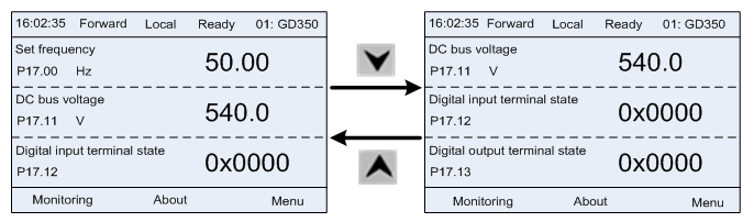
Figure 5–3 Stop parameter display state
Press  or
or  to switch between different display styles, including list display style and progress bar display style.
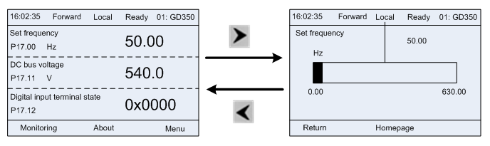
Figure 5–4 Stop parameter display state
The stop display parameter list is defined by the user, and each state variable function code can be added to the stop display parameter list as needed. The state variable which has been added to the stop display parameter list can also be deleted or shifted.
5.3.2 Running parameter display state
After receiving valid running command, the VFD will enter running state, and the keypad displays running state parameter with RUN indicator on the keypad turning on. Under running state, multiple
kinds of state parameters can be displayed. Press  or
or  to shift up or down.
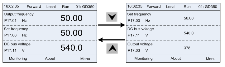
Figure 5–5 Running parameter display state
Press  or
or  to switch between different display styles, including list display style and progress bar display style.
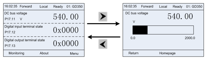
Figure 5–6 Running parameter display state
Under running state, multiple kinds of state parameters can be displayed. The running display parameter list is defined by the user, and each state variable function code can be added to the running display parameter list as needed. The state variable which has been added to the running display parameter list can also be deleted or shifted.
5.3.3 Fault alarm display state
The VFD enters fault alarm display state once fault signal is detected, and the keypad displays fault code and fault information with TRIP indicator on the keypad turning on. Fault reset operation can be carried out via STOP/RST key, control terminal or communication command.
The fault code will be kept displaying until fault is removed.
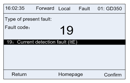
Figure 5–7 Fault alarm display state