5.5.11 Digital input
The GD350 IP54 series VFD carries four programmable digital input terminals and two HDI input terminals. The function of all the digital input terminals can be programmed by function codes. HDI input terminal can be set to act as high-speed pulse input terminal or common digital input terminal; if it is set to act as high-speed pulse input terminal, users can also set HDIA or HDIB high-speed pulse input to serve as the frequency reference and encoder signal input.
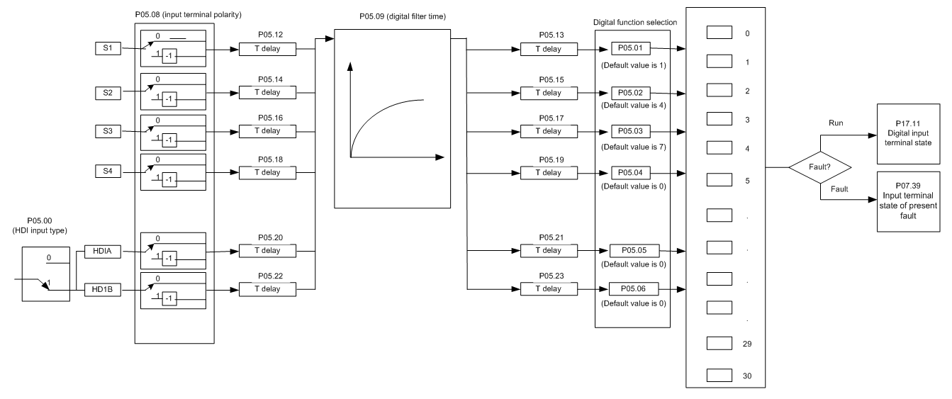
This parameter is used to set the corresponding function of digital multi-function input terminals.
Note: Two different multi-function input terminals cannot be set to the same function.
Set value | Function | Description |
0 | No function | The VFD does not act even if there is signal input; users can set the unused terminals to "no function" to avoid misacts. |
1 | Forward running (FWD) | Control the forward/reverse running of the VFD by external terminals. |
2 | Reverse running (REV) | |
3 | 3-wire control | Set the VFD running mode to the 3-wire control mode by this terminal. See P05.13 for details. |
4 | Forward jogging | Frequency when jogging, see P08.06, P08.07 and P08.08 for jogging acceleration/deceleration time. |
5 | Reverse jogging | |
6 | Coast to stop | The VFD blocks output, and the stop process of motor is uncontrolled by the VFD. This mode is applied in cases of large-inertia load and free stop time; its definition is the same with P01.08, and it is mainly used in remote control. |
7 | Fault reset | External fault reset function, its function is the same with the STOP/RST key on the keypad. This function can be used in remote fault reset. |
8 | Running pause | The VFD decelerates to stop, however, all the running parameters are in memory state, eg PLC parameter, wobbling frequency, and PID parameter. After this signal disappears, the VFD will revert to the state before stop. |
9 | External fault input | When external fault signal is transmitted to the VFD, the VFD releases fault alarm and stops. |
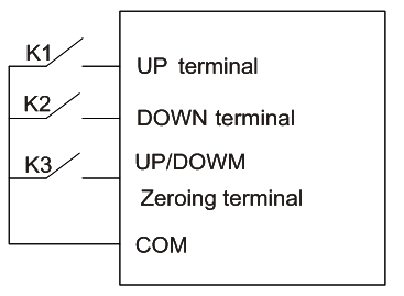
10 | Frequency increase (UP) | Used to change the frequency-increase/decrease command when the frequency is given by external terminals.
The terminal used to clear frequency-increase/decrease setting can clear the frequency value of auxiliary channel set by UP/DOWN, thus restoring the reference frequency to the frequency given by main reference frequency command channel. |
11 | Frequency decrease (DOWN) | |
12 | Clear frequency increase/decrease setting | |
13 | Switching between A setting and B setting | This function is used to switch between the frequency setting channels. A frequency reference channel and B frequency reference channel can be switched by no. 13 function; the combination channel set by P00.09 and the A frequency reference channel can be switched by no. 14 function; the combination channel set by P00.09 and the B frequency reference channel can be switched by no. 15 function. |
14 | Switching between combination setting and A setting | |
15 | Switching between combination setting and B setting | |
16 | Multi-step speed terminal 1 | 16-step speeds can be set by combining digital states of these four terminals. Note: Multi-step speed 1 is low bit, multi-step speed 4 is high bit. 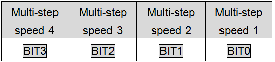 |
17 | Multi-step speed terminal 2 | |
18 | Multi-step speed terminal 3 | |
19 | Multi-step speed terminal 4 | |
20 | Multi-step speed pause | Pause multi-step speed selection function to keep the set value in present state. |
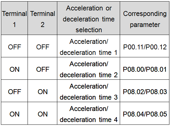
21 | Acceleration/deceleration time selection 1 | Use these two terminals to select four groups of acceleration/decoration time.
|
22 | Acceleration/deceleration time selection 2 | |
23 | Simple PLC stop reset | Restart simple PLC process and clear previous PLC state information. |
24 | Simple PLC pause | The program pauses during PLC execution, and keeps running in current speed step. After this function is cancelled, simple PLC keeps running. |
25 | PID control pause | PID is ineffective temporarily, and the VFD maintains current frequency output. |
26 | Wobbling frequency pause (stop at current frequency) | The VFD pauses at current output. After this function is canceled, it continues wobbling-frequency operation at current frequency. |
27 | Wobbling frequency reset (revert to center frequency) | The set frequency of VFD reverts to center frequency. |
28 | Counter reset | Zero out the counter state. |
29 | Switching between speed control and torque control | The VFD switches from torque control mode to speed control mode, or vice versa. |
30 | Acceleration/deceleration disabled | Ensure the VFD will not be impacted by external signals (except for stop command), and maintains current output frequency. |
31 | Counter trigger | Enable pulse counting of the counter. |
33 | Clear frequency increase/decrease setting temporarily | When the terminal is closed, the frequency value set by UP/DOWN can be cleared to restore the reference frequency to the frequency given by frequency command channel; when terminal is disconnected, it will revert to the frequency value after frequency increase/decrease setting. |
34 | DC brake | The VFD starts DC brake immediately after the command becomes valid. |
35 | Switching between motor 1 and motor 2 | When this terminal is valid, users can realize switch-over control of two motors. |
36 | Command switches to keypad | When this terminal is valid, the running command channel will switch to keypad compulsorily. If this function becomes invalid, the running command channel will revert to the original state. |
37 | Command switches to terminal | When this terminal is valid, the running command channel will switch to terminal compulsorily. If this function becomes invalid, the running command channel will revert to the original state. |
38 | Command switches to communication | When this terminal is valid, the running command channel will switch to communication compulsorily. If this function becomes invalid, the running command channel will revert to the original state. |
39 | Pre-exciting command | When this terminal is valid, motor pre-exciting will be started until this terminal becomes invalid. |
40 | Zero out power consumption quantity | After this command becomes valid, the power consumption quantity of the VFD will be zeroed out. |
41 | Maintain power consumption quantity | When this command is valid, current operation of the VFD will not impact the power consumption quantity. |
42 | Source of upper torque limit switches to keypad | When this command is valid, the upper limit of the torque will be set by keypad |
56 | Emergency stop | When this command is valid, the motor decelerate to emergency stop as per the time set by P01.26. |
57 | Motor over-temperature fault input | Motor stops at motor over-temperature fault input. |
59 | FVC switches to V/F control | When this terminal is valid in stop state, switch to SVPWM control. |
60 | Switch to FVC control | When this terminal is valid in stop state, switch to closed-loop vector control. |
61 | PID polarity switch-over | Switching the output polarity of PID, this terminal should be used in conjunction with P09.03 |
66 | Zero out the counter | Zero out the position counting value |
67 | Pulse increase | When the terminal function is valid, the pulse input is increased according to the P21.27 pulse speed. |
68 | Enable pulse superimposition | When the pulse superimposition is enabled, pulse increase and pulse decrease are effective. |
69 | Pulse decrease | When the terminal function is valid, the pulse input is decreased according to the P21.27 pulse speed. |
70 | Electronic gear selection | When the terminal is valid, the proportional numerator is switched to the P21.30 numerator of the 2nd command ratio. |
71 | Switch to mater | In stopped state, if the function is valid, the master is used. |
72 | Switch to slave | In stopped state, if the function is valid, the slave is used. |
73–79 | Reserved | / |
Related parameter list:
Function code | Name | Detailed parameter description | Default value |
P05.00 | HDI input type | 0x00–0x11 Ones: HDIA input type 0: HDIA is high-speed pulse input 1: HDIA is digital input Tens: HDIB input type 0: HDIB is high-speed pulse input 1: HDIB is digital input | 0x00 |
P05.01 | Function of S1 terminal | 0: No function 1: Forward running 2: Reverse running 3: 3-wire control 4: Forward jogging 5: Reverse jogging 6: Coast to stop 7: Fault reset 8: Running pause 9: External fault input 10: Frequency increase (UP) 11: Frequency decrease (DOWN) 12: Clear frequency increase/decrease setting 13: Switch-over between setup A and setup B 14: Switch-over between combination setting and A setting 15: Switch-over between combination setting and setup B 16: Multi-step speed terminal 1 17: Multi-step speed terminal 2 18: Multi-step speed terminal 3 19: Multi-step speed terminal 4 20: Multi-step speed pause 21: Acceleration/deceleration time selection 1 22: Acceleration/deceleration time selection 2 23: Simple PLC stop reset 24: Simple PLC pause 25: PID control pause 26: Wobbling frequency pause 27: Wobbling frequency reset 28: Counter reset 29: Switching between speed control and torque control 30: Acceleration/deceleration disabled 31: Counter trigger 32: Reserved 33: Clear frequency increase/decrease setting temporarily 34: DC brake 35: Switching between motor 1 and motor 2 36: Command switches to keypad 37: Command switches to terminal 38: Command switches to communication 39: Pre-exciting command 40: Zero out power consumption quantity 41: Maintain power consumption quantity 42: Source of upper torque limit switches to keypad 56: Emergency stop 57: Motor over-temperature fault input 59: Switch to V/F control 60: Switch to FVC control 61: PID polarity switch-over 66: Zero out encoder counting 67: Pulse increase 68: Enable pulse superimposition 69: Pulse decrease 70: Electronic gear selection 71: Switch to master 72: Switch to slave 73–79: Reserved | 1 |
P05.02 | Function of S2 terminal | 4 | |
P05.03 | Function of S3 terminal | 7 | |
P05.04 | Function of S4 terminal | 0 | |
P05.05 | Function of HDIA terminal | 0 | |
P05.06 | Function of HDIB terminal | 0 | |
P05.07 | Reserved variables | 0 | |
P05.08 | Polarity of input terminal | 0x00–0x3F | 0x00 |
P05.09 | Digital filter time | 0.000–1.000s | 0.010s |
P05.10 | Virtual terminal setting | 0x00–0x3F (0: disable, 1: enable) BIT0: S1 virtual terminal BIT1: S2 virtual terminal BIT2: S3 virtual terminal BIT3: S4 virtual terminal BIT4: HDIA virtual terminal BIT8: HDIB virtual terminal | 0x00 |
P05.11 | 2/3 wire control mode | 0: 2-wire control 5.5: 2-wire control 2 2: 3-wire control 1 3: 3-wire control 2 | 0 |
P05.12 | S1 terminal switch-on delay | 0.000–50.000s | 0.000s |
P05.13 | S1 terminal switch-off delay | 0.000–50.000s | 0.000s |
P05.14 | S2 terminal switch-on delay | 0.000–50.000s | 0.000s |
P05.15 | S2 terminal switch-off delay | 0.000–50.000s | 0.000s |
P05.16 | S3 terminal switch-on delay | 0.000–50.000s | 0.000s |
P05.17 | S3 terminal switch-off delay | 0.000–50.000s | 0.000s |
P05.18 | S4 terminal switch-on delay | 0.000–50.000s | 0.000s |
P05.19 | S4 terminal switch-off delay | 0.000–50.000s | 0.000s |
P05.20 | HDIA terminal switch-on delay | 0.000–50.000s | 0.000s |
P05.21 | HDIA terminal switch-off delay | 0.000–50.000s | 0.000s |
P05.22 | HDIB terminal switch-on delay | 0.000–50.000s | 0.000s |
P05.23 | HDIB terminal switch-off delay | 0.000–50.000s | 0.000s |
P07.39 | Input terminal state of present fault | / | 0 |
P17.12 | Digital input terminal state | / | 0 |
5.5.12 Digital output
The GD350 IP54 series VFD carries two groups of relay output terminals, one open collector Y output terminal and one high-speed pulse output (HDO) terminal. The function of all the digital output terminals can be programmed by function codes, of which the high-speed pulse output terminal HDO can also be set to high-speed pulse output or digital output by function code.
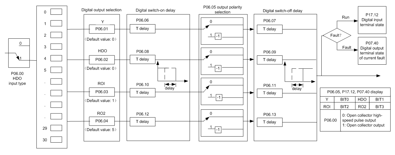
The table below lists the options for the above four function parameters, and users are allowed to select the same output terminal functions repetitively.
Set value | Function | Description |
0 | Invalid | Output terminal has no function |
1 | In running | Output ON signal when there is frequency output during running |
2 | In forward running | Output ON signal when there is frequency output during forward running |
3 | In reverse running | Output ON signal when there is frequency output during reverse running |
4 | In jogging | Output ON signal when there is frequency output during jogging |
5 | VFD fault | Output ON signal when VFD fault occurred |
6 | Frequency level detection FDT1 | Refer to P08.32 and P08.33 |
7 | Frequency level detection FDT2 | Refer to P08.34 and P08.35 |
8 | Frequency reached | Refer to P08.36 |
9 | Running in zero speed | Output ON signal when the VFD output frequency and reference frequency are both zero. |
10 | Reach upper limit frequency | Output ON signal when the running frequency reaches upper limit frequency |
11 | Reach lower limit frequency | Output ON signal when the running frequency reached lower limit frequency |
12 | Ready to run | Main circuit and control circuit powers are established, the protection functions do not act; when the VFD is ready to run, output ON signal. |
13 | In pre-exciting | Output ON signal during pre-exciting of the VFD |
14 | Overload pre-alarm | Output ON signal after the pre-alarm time elapsed based on the pre-alarm threshold; see P11.08–P15.50 for details. |
15 | Underload pre-alarm | Output ON signal after the pre-alarm time elapsed based on the pre-alarm threshold; see P15.51–P15.52 for details. |
16 | Simple PLC state completed | Output signal when current stage of simple PLC is completed |
17 | Simple PLC cycle completed | Output signal when a single cycle of simple PLC operation is completed |
23 | Virtual terminal output of Modbus communication | Output corresponding signal based on the set value of Modbus; output ON signal when it is set to 1, output OFF signal when it is set to 0 |
24 | Virtual terminal output of POROFIBUS/CANopen communication | Output corresponding signal based on the set value of PROFIBUS/CANopen; output ON signal when it is set to 1, output OFF signal when it is set to 0 |
25 | Virtual terminal output of Ethernet communication | Output corresponding signal based on the set value of Ethernet; output ON signal when it is set to 1, output OFF signal when it is set to 0. |
26 | DC bus voltage established | Output is valid when the bus voltage is above the undervoltage threshold of the inverter. |
27 | Z pulse output | Output is valid when the encoder Z pulse is arrived, and is invalid after 10 ms. |
28 | During pulse superposition | Output is valid when the pulse superposition terminal input function is valid |
29 | STO action | Output when STO fault occurred |
30 | Positioning completed | Output is valid when position control positioning is completed |
31 | Spindle zeroing completed | Output is valid when spindle zeroing is completed |
32 | Spindle scale-division completed | Output is valid when spindle scale-division is completed |
33 | In speed limit | Output is valid when the frequency is limited |
34 | Virtual terminal output of EtherCAT/PROFINET communication | The corresponding signal is output according to the set value of PROFINET communication. When it is set to 1, the ON signal is output, and when it is set to 0, the OFF signal is output. |
35 | Reserved | |
36 | Speed/position control switch-over completed | Output is valid when the mode switch-over is completed |
37–40 | Reserved | |
41 | C_Y1 | C_Y1 from PLC (set P27.00 to 1) |
42 | C_Y2 | C_Y2 from PLC (set P27.00 to 1) |
43 | C_HDO | C_HDO from PLC (set P27.00 to 1) |
44 | C_RO1 | C_RO1 from PLC (set P27.00 to 1) |
45 | C_RO2 | C_RO2 from PLC (set P27.00 to 1) |
46 | C_RO3 | C_RO3 from PLC (set P27.00 to 1) |
47 | C_RO4 | C_RO4 from PLC (set P27.00 to 1) |
48–63 | Reserved variables | / |
Related parameter list:
Function code | Name | Detailed parameter description | Default value |
P06.00 | HDO output type | 0: Open collector high-speed pulse output 1: Open collector output | 0 |
P06.01 | Y1 output selection | 0: Invalid 1: In running 2: In forward running 3: In reverse running 4: In jogging 5: VFD fault 6: Frequency level detection FDT1 7: Frequency level detection FDT2 8: Frequency reached 9: Running in zero speed 10: Reach upper limit frequency 11: Reach lower limit frequency 12: Ready to run 13: In pre-exciting 14: Overload pre-alarm 15: Underload pre-alarm 16: Simple PLC stage completed 17: Simple PLC cycle completed 18: Reach set counting value 19: Reach designated counting value 20: External fault is valid 21: Reserved 22: Reach running time 23: Virtual terminal output of Modbus communication 24: Virtual terminal output of POROFIBUS/CANopen communication 25: Virtual terminal output of Ethernet communication 26: DC bus voltage established 27: Z pulse output 28: During pulse superposition 29: STO action 30: Positioning completed 31: Spindle zeroing completed 32: Spindle scale-division completed 33: In speed limit 34: Virtual terminal output of EtherCAT/PROFINET communication 35: Reserved 36: Speed/position control switch-over completed 37: Any frequency reached 38–40: Reserved 41: C_Y1 from PLC (set P27.00 to 1) 42: C_Y2 from PLC (set P27.00 to1) 43: C_HDO from PLC (set P27.00 to 1) 44: C_RO1 from PLC (set P27.00 to 1) 45: C_RO2 from PLC (set P27.00 to 1) 46: C_RO3 from PLC 3 (set P27.00 to 1) 47: C_RO4 from PLC (set P27.00 to 1) 48–63: Reserved | 0 |
P06.02 | HDO output selection | 0 | |
P06.03 | Relay RO1 output selection | 1 | |
P06.04 | Relay RO2 output selection | 5 | |
P06.05 | Output terminal polarity selection | 0x00–0x0F | 0x00 |
P06.06 | Y switch-on delay | 0.000–50.000s | 0.000s |
P06.07 | Y switch-off delay | 0.000–50.000s | 0.000s |
P06.08 | HDO switch-on delay | 0.000–50.000s (valid only when P06.00=1) | 0.000s |
P06.09 | HDO switch-off delay | 0.000–50.000s (valid only when P06.00=1) | 0.000s |
P06.10 | Relay RO1 switch-on delay | 0.000–50.000s | 0.000s |
P06.11 | Relay RO1 switch-off delay | 0.000–50.000s | 0.000s |
P06.12 | Relay RO2 switch-on delay | 0.000–50.000s | 0.000s |
P06.13 | Relay RO2 switch-off delay | 0.000–50.000s | 0.000s |
P07.40 | Output terminal state of present fault | / | 0 |
P17.13 | Digital output terminal state | / | 0 |
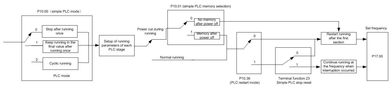
5.5.13 Simple PLC
Simple PLC is a multi-step speed generator, and the VFD can change the running frequency and direction automatically based on the running time to fulfill process requirements. Previously, such function was realized with external PLC, while now, the VFD itself can achieve this function.
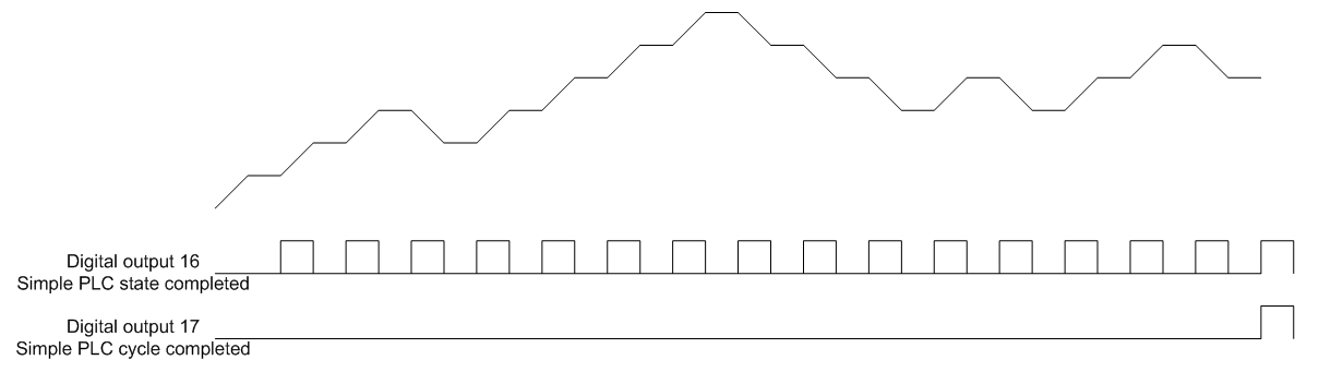
The GD350 IP54 series VFD can realize 16-step speeds control, and provide four groups of acceleration/deceleration time for users to choose from.
After the configured PLC completes a cycle (or stage), an ON signal can be output by the multi-function relay.
Related parameter list:
Function code | Name | Detailed parameter description | Default value |
P05.01–P05.06 | Digital input function | 23: Simple PLC stop reset 24: Simple PLC pause 25: PID control pause | |
P06.01–P06.04 | Digital output function | 16: Simple PLC stage reached 17: Simple PLC cycle reached | |
P10.00 | Simple PLC mode | 0: Stop after running once 1: Keep running in the final value after running once 2: Cyclic running | 0 |
P10.01 | Simple PLC memory selection | 0: No memory after power down 1: Memory after power down | 0 |
P10.02 | Multi-step speed 0 | -100.0–100.0% | 0.0% |
P10.03 | Running time of 0th step | 0.0–6553.5s (min) | 0.0s |
P10.04 | Multi-step speed 1 | -100.0–100.0% | 0.0% |
P10.05 | Running time of 1st step | 0.0–6553.5s (min) | 0.0s |
P10.06 | Multi-step speed 2 | -100.0–100.0% | 0.0% |
P10.07 | Running time of 2nd step | 0.0–6553.5s (min) | 0.0s |
P10.08 | Multi-step speed 3 | -100.0–100.0% | 0.0% |
P10.09 | Running time of 3rd step | 0.0–6553.5s (min) | 0.0s |
P10.10 | Multi-step speed 4 | -100.0–100.0% | 0.0% |
P10.11 | Running time of 4th step | 0.0–6553.5s (min) | 0.0s |
P10.12 | Multi-step speed 5 | -100.0–100.0% | 0.0% |
P10.13 | Running time of 5th step | 0.0–6553.5s (min) | 0.0s |
P10.14 | Multi-step speed 6 | -100.0–100.0% | 0.0% |
P10.15 | Running time of 6th step | 0.0–6553.5s (min) | 0.0s |
P10.16 | Multi-step speed 7 | -100.0–100.0% | 0.0% |
P10.17 | Running time of 7th step | 0.0–6553.5s (min) | 0.0s |
P10.18 | Multi-step speed 8 | -100.0–100.0% | 0.0% |
P10.19 | Running time of 8th step | 0.0–6553.5s (min) | 0.0s |
P10.20 | Multi-step speed 9 | -100.0–100.0% | 0.0% |
P10.21 | Running time of 9th step | 0.0–6553.5s (min) | 0.0s |
P10.22 | Multi-step speed 10 | -100.0–100.0% | 0.0% |
P10.23 | Running time of 10th step | 0.0–6553.5s (min) | 0.0s |
P10.24 | Multi-step speed 11 | -100.0–100.0% | 0.0% |
P10.25 | Running time of 11th step | 0.0–6553.5s (min) | 0.0s |
P10.26 | Multi-step speed 12 | -100.0–100.0% | 0.0% |
P10.27 | Running time of 12th step | 0.0–6553.5s (min) | 0.0s |
P10.28 | Multi-step speed 13 | -100.0–100.0% | 0.0% |
P10.29 | Running time of 13th step | 0.0–6553.5s (min) | 0.0s |
P10.30 | Multi-step speed 14 | -100.0–100.0% | 0.0% |
P10.31 | Running time of 14th step | 0.0–6553.5s (min) | 0.0s |
P10.32 | Multi-step speed 15 | -100.0–100.0% | 0.0% |
P10.33 | Running time of 15th step | 0.0–6553.5s (min) | 0.0s |
P10.36 | PLC restart mode | 0: Restart from the first section 1: Continue running at the frequency when interruption occurred | 0 |
P10.34 | Acceleration/deceleration time of 0–7 stage of simple PLC | 0x0000–0XFFFF | 0000 |
P10.35 | Acceleration/deceleration time of 8–15 stage of simple PLC | 0x0000–0XFFFF | 0000 |
P17.00 | Set frequency | 0.00Hz–P00.03 (max. output frequency) | 0.00Hz |
P17.27 | Acutal stage of simple PLC | Displays the present stage of the simple PLC function. | 0 |
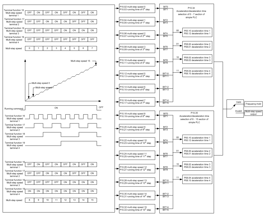
5.5.14 Multi-step speed running
Set the parameters used in multi-step speed running. the GD350 IP54 series VFD can set 16-step speeds, which are selectable by multi-step speed terminals 1–4, corresponding to multi-step speed 0 to multi-step speed 15.
Related parameter list:
Function code | Name | Detailed parameter description | Default value |
P05.01–P05.06 | Digital input function selection | 16: Multi-step speed terminal 1 17: Multi-step speed terminal 2 18: Multi-step speed terminal 3 19: Multi-step speed terminal 4 20: Multi-step speed pause | |
P10.02 | Multi-step speed 0 | -100.0–100.0% | 0.0% |
P10.03 | Running time of 0th step | 0.0–6553.5s (min) | 0.0s |
P10.04 | Multi-step speed 1 | -100.0–100.0% | 0.0% |
P10.05 | Running time of 1st step | 0.0–6553.5s (min) | 0.0s |
P10.06 | Multi-step speed 2 | -100.0–100.0% | 0.0% |
P10.07 | Running time of 2nd step | 0.0–6553.5s (min) | 0.0s |
P10.08 | Multi-step speed 3 | -100.0–100.0% | 0.0% |
P10.09 | Running time of 3rd step | 0.0–6553.5s (min) | 0.0s |
P10.10 | Multi-step speed 4 | -100.0–100.0% | 0.0% |
P10.11 | Running time of 4th step | 0.0–6553.5s (min) | 0.0s |
P10.12 | Multi-step speed 5 | -100.0–100.0% | 0.0% |
P10.13 | Running time of 5th step | 0.0–6553.5s (min) | 0.0s |
P10.14 | Multi-step speed 6 | -100.0–100.0% | 0.0% |
P10.15 | Running time of 6th step | 0.0–6553.5s (min) | 0.0s |
P10.16 | Multi-step speed 7 | -100.0–100.0% | 0.0% |
P10.17 | Running time of 7th step | 0.0–6553.5s (min) | 0.0s |
P10.18 | Multi-step speed 8 | -100.0–100.0% | 0.0% |
P10.19 | Running time of 8th step | 0.0–6553.5s (min) | 0.0s |
P10.20 | Multi-step speed 9 | -100.0–100.0% | 0.0% |
P10.21 | Running time of 9th step | 0.0–6553.5s (min) | 0.0s |
P10.22 | Multi-step speed 10 | -100.0–100.0% | 0.0% |
P10.23 | Running time of 10th step | 0.0–6553.5s (min) | 0.0s |
P10.24 | Multi-step speed 11 | -100.0–100.0% | 0.0% |
P10.25 | Running time of 11th step | 0.0–6553.5s (min) | 0.0s |
P10.26 | Multi-step speed 12 | -100.0–100.0% | 0.0% |
P10.27 | Running time of 12th step | 0.0–6553.5s (min) | 0.0s |
P10.28 | Multi-step speed 13 | -100.0–100.0% | 0.0% |
P10.29 | Running time of 13th step | 0.0–6553.5s (min) | 0.0s |
P10.30 | Multi-step speed 14 | -100.0–100.0% | 0.0% |
P10.31 | Running time of 14th step | 0.0–6553.5s (min) | 0.0s |
P10.32 | Multi-step speed 15 | -100.0–100.0% | 0.0% |
P10.33 | Running time of 15th step | 0.0–6553.5s (min) | 0.0s |
P10.34 | Acceleration/decoration time selection of 0–7 section of simple PLC | 0x0000–0XFFFF | 0000 |
P10.35 | Acceleration/decoration time selection of 8–15 section of simple PLC | 0x0000–0XFFFF | 0000 |
P17.27 | Acutal stage of simple PLC | Displays the present stage of the simple PLC function. | 0 |
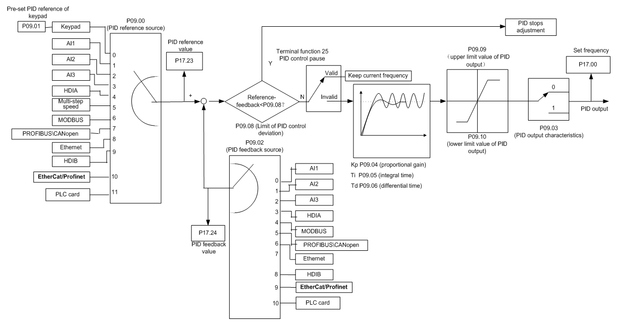
5.5.15 PID control
PID control, a common mode for process control, is mainly used to adjust the VFD output frequency or output voltage through performing scale-division, integral and differential operations on the difference between feedback signal of controlled variables and signal of the target, thus forming a negative feedback system to keep the controlled variables above the target. It is suitable for flow control, pressure control, temperature control, etc. Diagram of basic principles for output frequency regulation is shown in the figure below.
Introduction to the working principles and control methods for PID control
Proportional control (Kp):
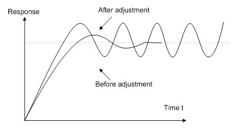
When the feedback is different from the reference, the output will be proportional to the difference. If such a difference is constant, the regulating variable will also be constant. Proportional control can respond to feedback changes rapidly, however, it cannot eliminate the difference by itself. A larger the proportional gain indicates a faster regulating speed, but a too large gain will result in oscillation. To solve this problem, set the integral time to a large value and the differential time to 0, run the system only with proportional control, and then change the reference to observe the difference (that is, static difference) between the feedback signal and reference. If the static difference occurs in the direction of reference change (such as reference increase, where the feedback is always less than the reference after system stabilizes), continue increasing the proportional gain; otherwise, decrease the proportional gain. Repeat this process until the static difference becomes small.
Integral time (Ti):
When the feedback is different from the reference, the output will be proportional to the difference. If such a difference is constant, the regulating variable will also be constant. Proportional control can respond to feedback changes rapidly, however, it cannot eliminate the difference by itself. A larger the proportional gain indicates a faster regulating speed, but a too large gain will result in oscillation. To solve this problem, set the integral time to a large value and the differential time to 0, run the system only with proportional control, and then change the reference to observe the difference (that is, static difference) between the feedback signal and reference. If the static difference occurs in the direction of reference change (such as reference increase, where the feedback is always less than the reference after system stabilizes), continue increasing the proportional gain; otherwise, decrease the proportional gain. Repeat this process until the static difference becomes small.
Derivative time (Td):
When the deviation between feedback and reference changes, output the regulating variable which is proportional to the deviation variation rate, and this regulating variable is only related to the direction and magnitude of the deviation variation rather than the direction and magnitude of the deviation itself. Differential control is used to control the feedback signal variation based on the variation trend. Differential regulator should be used with caution as it may easily enlarge the system interferences, especially those with high variation frequency.
When frequency command selection (P00.06, P00. 07) is 7, or channel of voltage setup (P04.27) is 6, the running mode of VFD is process PID control.
5.5.15.1 General procedures for PID parameter setup
a. Determining proportional gain P
When determining proportional gain P, first, remove the integral term and derivative term of PID by making Ti=0 and Td=0 (see PID parameter setup for details), thus turning PID into pure proportional control. Set the input to 60%–70% of the max. allowable value, and increase proportional gain P gradually from 0 until system oscillation occurred, and then in turn, decrease proportional gain P gradually from current value until system oscillation disappears, record the proportional gain P at this point and set the proportional gain P of PID to 60%–70% of current value. This is whole commissioning process of proportional gain P.
b. Determine integral time Ti
After proportional gain P is determined, set the initial value of a larger integral time Ti, and decrease Ti gradually until system oscillation occurred, and then in turn, increase Ti until system oscillation disappears, record the Ti at this point, and set the integral time constant Ti of PID to 150%–180% of current value. This is the commissioning process of integral time constant Ti.
c. Determining derivative time Td
The derivative time Td is generally set to 0.
If users need to set Td to another value, set in the same way with P and Ti, namely set Td to 30% of the value when there is no oscillation.
d. Empty system load, perform load-carrying joint debugging, and then fine-tune PID parameter until fulfilling the requirement.
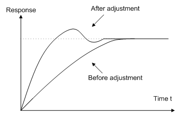
5.5.15.2 How to fine-tune PID
After setting the parameters controlled by PID, users can fine-tune these parameters by the following means.
Control overmodulation: When overmodulation occurred, shorten the derivative time (Td) and prolong integral time (Ti).
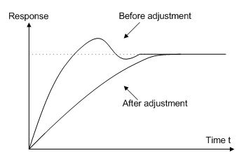
Stabilize the feedback value as fast as possible: when overmodulation occurred, shorten integral time (Ti) and prolong derivative time (Td) to stabilize control as fast as possible.
Control long-term vibration: If the cycle of periodic vibration is longer than the set value of integral time (Ti), it indicates the integral action is too strong, prolong the integral time (Ti) to control vibration.
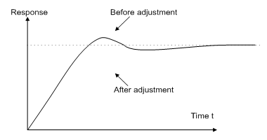
Control short-term vibration: If the vibration cycle is short is almost the same with the set value of derivative time (Td), it indicates derivative action is too strong, shorten the derivative time (Td) to control vibration. When derivative time (Td) is set to 0.00 (namely no derivative control), and there is no way to control vibration, decrease the proportional gain.
Related parameter list:
Function code | Name | Detailed parameter description | Defaultvalue |
P09.00 | PID reference source | 0: Keypad (P09.01) 1: AI1 2: AI2 3: AI3 4: High-speed pulse HDIA 5: Multi-step 6: Modbus communication 7: PROFIBUS/CANopen/DeviceNet communication 8: Ethernet communication 9: High-speed pulse HDIB 10: EtherCAT/PROFINET communication 11: Programmable extension card 12: Reserved | 0 |
P09.01 | Pre-set PID reference of keypad | -100.0%–100.0% | 0.0% |
P09.02 | PID feedback source | 0: AI1 1: AI2 2: AI3 3: High-speed pulse HDIA 4: Modbus communication 5: PROFIBUS/CANopen/DeviceNet communication 6: Ethernet communication 7: High-speed pulse HDIB 8: EtherCAT/PROFINET communication 9: Programmable extension card 10: Reserved | 0 |
P09.03 | PID output characteristics | 0: PID output is positive characteristic 1: PID output is negative characteristic | 0 |
P09.04 | Proportional gain (Kp) | 0.00–100.00 | 1.80 |
P09.05 | Integral time (Ti) | 0.05.50.00s | 0.90s |
P09.06 | Differential time (Td) | 0.00–10.00s | 0.00s |
P09.07 | Sampling cycle (T) | 0.000–10.000s | 0.100s |
P09.08 | Limit of PID control deviation | 0.0–100.0% | 0.0% |
P09.09 | Upper limit value of PID output | P09.10–100.0% (max. frequency or voltage) | 100.0% |
P09.10 | Lower limit value of PID output | -100.0%–P09.09 (max. frequency or voltage) | 0.0% |
P09.11 | Feedback offline detection value | 0.0–100.0% | 0.0% |
P09.12 | Feedback offline detection time | 0.0–3600.0s | 1.0s |
P09.13 | PID control selection | 0x0000–0x5.51 Ones: 0: Continue integral control after the frequency reaches upper/lower limit 1: Stop integral control after the frequency reaches upper/lower limit Tens: 0: The same with the main reference direction 1: Contrary to the main reference direction Hundreds: 0: Limit as per the max. frequency 1: Limit as per A frequency Thousands: 0: A+B frequency, acceleration /deceleration of main reference A frequency source buffering is invalid 1: A+B frequency, acceleration/ deceleration of main reference A frequency source buffering is valid, acceleration/deceleration is determined by P08.04 (acceleration time 4). | 0x0001 |
P09.14 | Low frequency proportional gain (Kp) | 0.00–100.00 | 1.00 |
P09.15 | ACC/DEC time of PID command | 0.0–1000.0s | 0.0s |
P09.16 | PID output filter time | 0.000–10.000s | 0.000s |
P09.17 | Reserved | -100.0–100.0% | 0.0% |
P09.18 | Low frequency integral time (Ti) | 0.00–10.00s | 0.90s |
P09.19 | Low frequency differential time (Td) | 0.00–10.00s | 0.00s |
P09.20 | Low frequency point for PID parameter switching | 0.00–P09.21 | 5.00Hz |
P09.21 | High frequency point for PID parameter switching | P09.20–P00.04 | 10.00Hz |
P17.00 | Set frequency | 0.00Hz–P00.03 (max. output frequency) | 0.00Hz |
P17.23 | PID reference value | -100.0–100.0% | 0.0% |
P17.24 | PID feedback value | -100.0–100.0% | 0.0% |
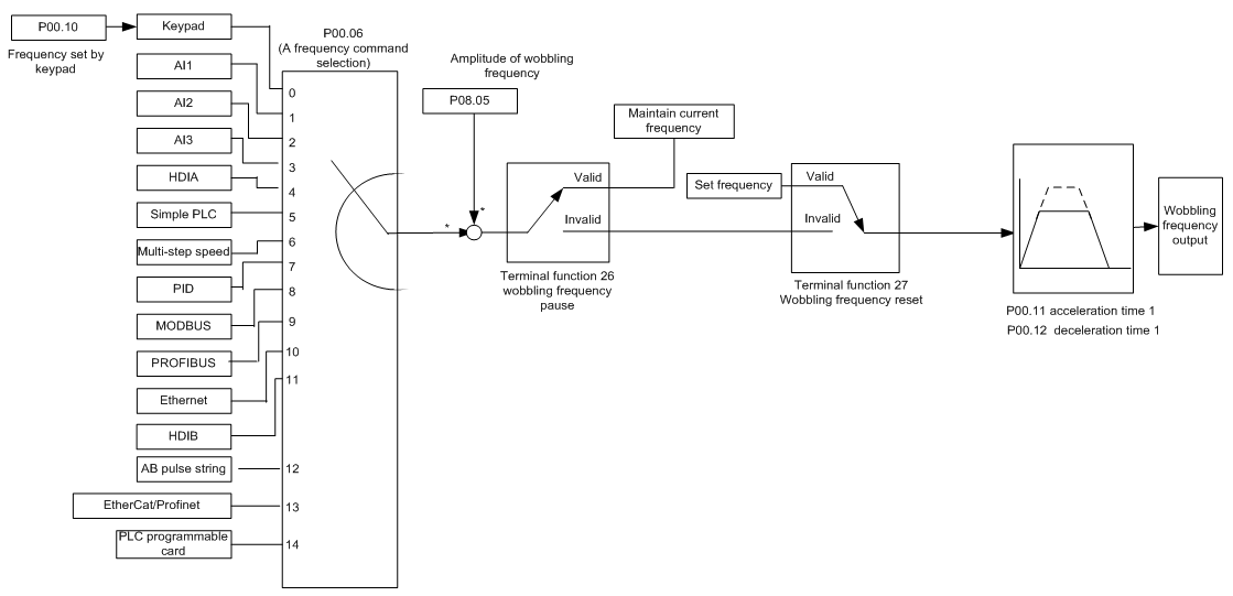
5.5.16 Run at wobbling frequency
Wobbling frequency is mainly applied in cases where transverse movement and winding functions are needed like textile and chemical fiber industries. The typical working process is shown as below.
Function code | Name | Detailed parameter description | Default value |
P00.03 | Max. output frequency | P00.03–400.00Hz | 50.00Hz |
P00.06 | A frequency command selection | 0: Set via keypad 1: Set via AI1 2: Set via AI2 3: Set via AI3 4: Set via high speed pulse HDIA 5: Set via simple PLC program 6: Set via multi-step speed running 7: Set via PID control 8: Set via Modbus communication 9: Set via PROFIBUS/CANopen/ DeviceNet communication 10: Set via Ethernet communication 11: Set via high speed pulse HDIB 12: Set via pulse string AB 13: Set via EtherCAT/PROFINET communication 14: Set via PLC card | 0 |
P00.11 | Acceleration time 1 | 0.0–3600.0s | Depends on model |
P00.12 | Deceleration time 1 | 0.0–3600.0s | Depends on model |
P05.01–P05.06 | Digital input function selection | 26: Wobbling frequency pause (stop at current frequency) 27: Wobbling frequency reset (revert to center frequency) | / |
P08.15 | Amplitude of wobbling frequency | 0.0–100.0% (relative to set frequency) | 0.0% |
P08.16 | Amplitude of jump frequency | 0.0–50.0% (relative to amplitude of wobbling frequency) | 0.0% |
P08.17 | Wobbling frequency rise time | 0.1–3600.0s | 5.0s |
P08.18 | Wobbling frequency fall time | 0.1–3600.0s | 5.0s |
5.5.17 Local encoder input
The GD350 IP54 series VFD supports pulse count function by inputting the count pulse from HDI high-speed pulse port. When the actual count value is no less than the set value, digital output terminal will output count-value-reached pulse signal, and the corresponding count value will be zeroed out.
Function code | Name | Detailed parameter description | Default value |
P05.00 | HDI input type | 0x00–0x11 Ones: HDIA input type 0: HDIA is high-speed pulse input 1: HDIA is digital input Tens: HDIB input type 0: HDIB is high-speed pulse input 1: HDIB is digital input | 0x00 |
P05.38 | HDIA high-speed pulse input function | 0: Set input via frequency 1: Reserved 2: Input via encoder, used in combination with HDIB | 0 |
P05.44 | HDIB high-speed pulse input function selection | 0: Set input via frequency 1: Reserved 2: Input via encoder, used in combination with HDIA | 0 |
P20.15 | Speed measurement mode | 0: PG card 1: local; realized by HDIA and HDIB; supports incremental 24V encoder only | 0 |
P18.00 | Actual frequency of encoder | -999.9–3276.7Hz | 0.0Hz |
5.5.18 Commissioning procedures for closed-loop control, position control and spindle positioning
1. Commissioning procedures for closed-loop vector control of asynchronous motor
Step 1: Restore to default value via keypad
Step 2: Set P00.03, P00.04 and P02 group motor nameplate parameters
Step 3: Motor parameter autotuning
Carry out rotary parameter autotuning or static parameter autotuning via keypad, if the motor can be disconnected from load, then it is users can carry out rotary parameter autotuning; otherwise, carry out static parameter autotuning, the parameter obtained from autotuning will be saved in P02 motor parameter group automatically.
Step 4: Verify whether the encoder is installed and set properly
a) Confirm the encoder direction and parameter setup
Set P20.01 (encoder pulse-per-revolution), set P00.00=2 and P00.10=20Hz, and run the VFD, at this point, the motor rotates at 20Hz, observe whether the speed measurement value of P18.00 is correct, if the value is negative, it indicates the encoder direction is reversed, under such situation, set P20.02 to 1; if the speed measurement value deviates greatly, it indicates P20.01 is set improperly. Observe whether P18.02 (encoder Z pulse count value) fluctuates, if yes, it indicates the encoder suffers interference or P20.01 is set improperly, requiring users to check the wiring and the shielding layer.
b) Determine Z pulse direction
Set P00.10=20Hz, and set P00.13 (running direction) to forward and reverse direction respectively to observe whether the difference value of P18.02 is less than 5, if the difference value remains to be larger than 5 after setting Z pulse reversal function of P20.02, power off and exchange phase A and phase B of the encoder, and then observe the difference between the value of P18.02 during forward and reverse rotation. Z pulse direction only affects the forward/reverse positioning precision of the spindle positioning carried out with Z pulse.
Step 5: Closed-loop vector pilot-run
Set P00.00=3, and carry out closed-loop vector control, adjust P00.10 and speed loop and current loop PI parameter in P03 group to make it run stably in the whole range.
Step 6: Flux-weakening control
Set flux-weakening regulator gain P03.26=0–8000, and observe the flux-weakening control effect. P03.22–P03.24 can be adjusted as needed.
2. Commissioning procedures for closed-loop vector control of synchronous motor
Step 1: Set P00.18=1, restore to default value
Step 2: Set P00.00=3 (VC) , set P00.03, P00.04, and motor nameplate parameters in P02 group.
Step 3: Set P20.01 encoder parameters
When the encoder is resolver-type encoder, set the encoder pulse count value to (resolver pole pair number × 1024), eg, if pole pair number is 4, set P20.01 to 4096.
Step 4: Ensure the encoder is installed and set correctly
When motor stops, observe whether P18.21 (resolver angle) fluctuates, if it fluctuates sharply, check the wiring and grounding. Rotates the motor slowly, observe whether P18.21 changes accordingly, if yes, it indicates motor is connected correctly; if the value of P18.02 keeps constant at a non-zero value after rotating for multiple circles, it indicates encoder Z signal is correct.
Step 5: Autotuning of initial position of magnetic pole
Set P20.11=2 or 3 (3: rotary autotuning; 2: static autotuning), press RUN key to run the VFD.
a) Rotary autotuning (P20.11 = 3)
Detect the position of current magnetic pole when autotuning starts, and then accelerates to 10Hz, autotuning corresponding magnetic pole position of encoder Z pulse, and decelerate to stop.
During running, if ENC1O or ENC1D fault occurred, set P20.02=1 and carry out autotuning again.
After autotuning is done, the angle obtained from autotuning will be saved in P20.09 and P20.10 automatically.
b) Static autotuning
In cases where the load can be disconnected, it is recommended to adopt rotary autotuning (P20.11=3) as it has high angle precision. If the load cannot be disconnected, users can adopt static autotuning (P20.11=2). The magnetic pole position obtained from autotuning will be saved in P20.09 and P20.10.
Step 6: Closed-loop vector pilot-run
Adjust P00.10 and speed loop and current loop PI parameter in P03 group to make it run stably in the whole range. If oscillation occurred, reduce the value of P03.00, P03.03, P03.09 and P03.10. If current oscillation noise occurred during low speed, adjust P20.05.
Note: It is necessary to re-determine P20.02 (encoder direction) and carry out magnetic pole position autotuning again if the wiring of motor or encoder is changed.
3. Commissioning procedures for pulse string control
Pulse input is operated based on closed-loop vector control; speed detection is needed in the subsequent spindle positioning, zeroing operation and division operation.
Step 1: Restore to default value by keypad
Step 2: Set P00.03, P00.04 and motor nameplate parameters in P02 group
Step 3: Motor parameter autotuning: rotary parameter autotuning or static parameter autotuning
Step 4: Verity the installation and settings of encoder. Set P00.00=3 and P00.10=20Hz to run the system, and check the control effect and performance of the system.
Step 5: Set P21.00=0001 to set positioning mode to position control, namely pulse-string control. There are four kinds of pulse command modes, which can be set by P21.01 (pulse command mode).
Under position control mode, users can check high bit and low bit of position reference and feedback, P18.02 (count value of Z pulse), P18.00 (actual frequency of encoder), P18.17 (pulse command frequency) and P18.19 (position regulator output) via P18, through which users can figure out the relation between P18.8 (position of position reference point) and P18.02, pulse command frequency P18.17, pulse command feedforward P18.18 and position regulator output P18.19.
Step 6: The position regulator has two gains, namely P21.02 and P21.03, and they can be switched by speed command, torque command and terminals.
Step 7: When P21.08 (output limit of position controller) is set to 0, the position control will be invalid, and at this point, the pulse string acts as frequency source, P25.53 (position feedforward gain) should be set to 100%, and the speed acceleration/deceleration time is determined by the acceleration /deceleration time of pulse string, the pulse string acceleration/deceleration time of the system can be adjusted. If the pulse string acts as the frequency source in speed control, users can also set P21.00 to 0000, and set the frequency source reference P00.06 or P00.07 to 12 (set by pulse string AB), at this point, the acceleration/deceleration time is determined by the acceleration/deceleration time of the VFD, meanwhile, the parameters of pulse string AB is still set by P21 group. In speed mode, the filter time of pulse string AB is determined by P21.29.
Step 8: The input frequency of pulse string is the same with the feedback frequency of encoder pulse, the relation between them can be changed by altering P25.51 (numerator of position command ratio) and P25.52 (denominator of position command ratio)
Step 9: When running command or servo enabling is valid (by setting P21.00 or terminal function 63), it will enter pulse string servo running mode.
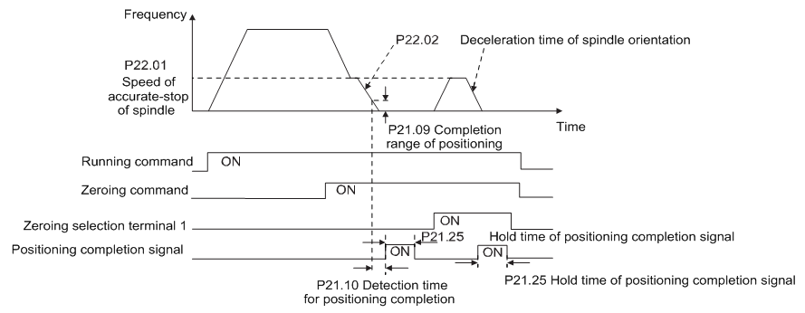
4. Commissioning procedures for spindle positioning
Spindle orientation is to realize orientation functions like zeroing and division based on closed-loop vector control
Step 1–4: These four steps are the same with the first four steps of the commissioning procedures for closed-loop vector control, which aim to fulfill the control requirements of closed-loop vector control, thus realizing spindle positioning function in either position control or speed control mode.
Step 5: Set P22.00.bit0=1 to enable spindle positioning, set P22.00.bit1 to select spindle zero input. If the system adopts encoder for speed measurement, set P22.00.bit1 to 0 to select Z pulse input; if the system adopts photoelectric switch for speed measurement, set P22.00.bit1 to 1 to select photoelectric switch as zero input; set P22.00.bit2 to select zero search mode, set P22.00.bit3 to enable or disable zero calibration, and select zero calibration mode by setting P22.00.bit7.
Step 6: Spindle zeroing operation
a) Select the positioning direction by setting P22.00.bit4;
b) There are four zero positions in P22 group, users can choose one out of four zeroing positions by setting zeroing input terminal selection (46, 47) in P05 group. When executing zeroing function, the motor will stop accurately at corresponding zeroing position according to the set positioning direction, which can be viewed via P18.10;
c) The positioning length of spindle zeroing is determined by the deceleration time of accurate-stop and the speed of accurate-stop;
Step 7: Spindle division operation
There are seven scale-division positions in P22 group, users can choose one out of seven scale-division positions by setting scale-division input terminal selection (48, 49, 50) in P05 group. Enable corresponding scale-division terminal after the motor stops accurately, and the motor will check the scale-division position state and switch to corresponding position incrementally, at this point, users can check P18.09.
Step 8: Priority level of speed control, position control and zeroing
The priority level of speed running is higher than that of the scale division, when the system runs in scale-division mode, if spindle orientation is prohibited, the motor will turn to speed mode or position mode.
The priority level of zeroing is higher than that of the scale division.
Scale-division command is valid when the scale-division terminal is from 000 state to non-000 state, eg, in 000–011, the spindle executes scale division 3. The transition time during terminal switch-over needs to be less than 10ms; otherwise, wrong scale division command may be executed.
Step 9: Hold positioning
The position loop gain during positioning is P21.03; while the position loop gain in positioning-completion-hold state is P21.02. In order to keep sufficient position-hold force and ensure no system oscillation occurred, adjust P03.00, P03.01, P20.05 and P21.02.
Step 10: Positioning command selection (bit6 of P22.00)
Electric level signal: Positioning command (zeroing and scale division) can be executed only when there is running command or the servo is enabled.
Step 11: Spindle reference point selection (bit0 of P22.00)
Encoder Z pulse positioning supports the following spindle positioning modes:
a) the encoder is installed on the motor shaft, the motor shaft and spindle is 5.5 rigid connection;
b) the encoder is installed on the motor shaft, the motor shaft and spindle is 5.5 belt connection;
At this point, the belt may slip during high-speed running and cause inaccurate positioning, it is recommended to install proximity switch on the spindle.
c) The encoder is installed on the spindle, and the motor shaft is connected to the spindle with belt, the drive ratio is not necessarily 5.5;
At this point, set P20.06 (speed ratio of the mounting shaft between motor and encoder), and set P22.14 (spindle drive ratio) to 1. As the encoder is not installed on the motor, the control performance of closed-loop vector will be affected.
Proximity switch positioning supports the following spindle positioning modes:
a) The encoder is installed on the motor shaft, the drive ratio between motor shaft and spindle is not necessarily 5.5;
At this point, it is required to set P22.14 (spindle drive ratio).
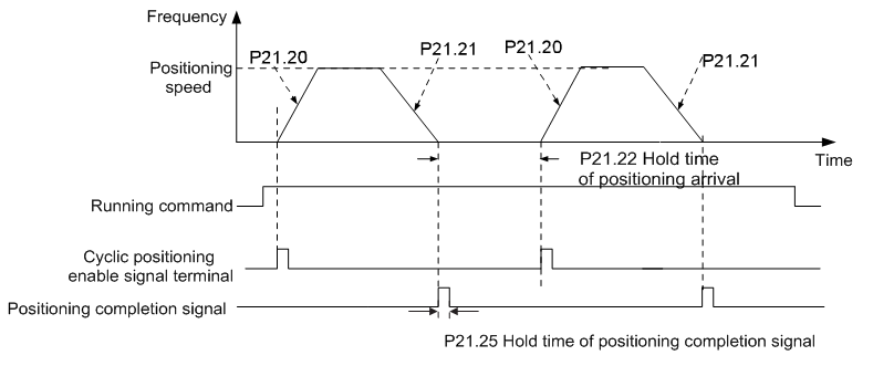
5. Commissioning procedures for digital positioning
The diagram for digital positioning is shown below.
Step 1–4: These four steps are the same with the first four steps of the commissioning procedures for closed-loop vector control, which aim to fulfill the control requirements of closed-loop vector control.
Step 5: Set P21.00=0011 to enable digital positioning. Set P25.57, P25.51 and P25.52 (set positioning displacement) according to actual needs ; set P25.58 and P25.59 (set positioning speed); set P21.20 and P21.21 (set acceleration/deceleration time of positioning).
Step 6: Single positioning operation
Set P25.56.bit1=0, and the motor will carry out single positioning action and stay in the positioning position according to the setup in step 5.
Step 7: Cyclic positioning operation
Set P25.56.bit5.5 to enable cyclic positioning. The cyclic positioning is divided into continuous mode and repetitive mode; users can also carry out cyclic positioning through terminal function (no. 55, enable digital positioning cycle)
6. Commissioning procedures for positioning of photoelectric switch
Photoelectric switch positioning is to realize positioning function based on closed-loop vector control.
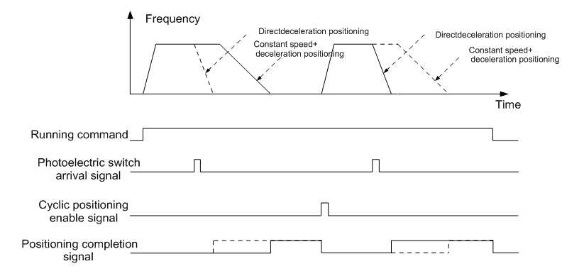
Step 1–4: These four steps are the same with the first four steps of the commissioning procedures for closed-loop vector control, which aim to fulfill the control requirements of closed-loop vector control.
Step 5: Set P21.00=0021 to enable photoelectric switch positioning, the photoelectric switch signal can be connected to S8 terminal only, and set P05.08=43, meanwhile, set P25.57, P25.51 and P25.52 (set positioning displacement) based on actual needs; set P21.21 (deceleration time of positioning), however, when present running speed is too fast or the set positioning displacement is too small, the deceleration time of positioning will be invalid, and it will enter direct deceleration positioning mode.
Step 6: Cyclic positioning
After positioning is done, the motor will stay in current position. Users can set cyclic positioning through input terminal function selection (55: enable cyclic digital positioning) in P05 group; when the terminal receives cyclic positioning enable signal (pulse signal), the motor will continue running in the set speed as per the speed mode and re-enter positioning state after encountering photoelectric switch.
(7) Hold positioning
The position loop gain during positioning is P21.03; while the position loop gain in positioning-completion-hold state is P21.02. In order to keep sufficient position-hold force and ensure no system oscillation occurred, adjust P03.00, P03.01, P20.05 and P21.02.
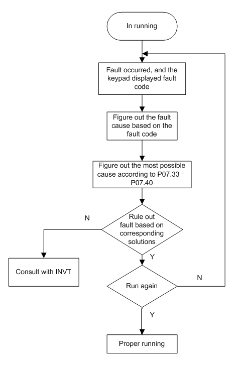
5.5.19 Fault handling
GD350 series VFD provides abundant information concerning fault handling for the convenience of the users.
Related parameter list:
Function code | Name | Detailed parameter description | Default value |
P07.27 | Type of present fault | 0: No fault 1: Inverter unit U phase protection (OUt1) 2: Inverter unit V phase protection (OUt2) 3: Inverter unit W phase protection (OUt3) 4: Overcurrent during acceleration (OC1) 5: Overcurrent during deceleration (OC2) 6: Overcurrent during constant speed (OC3) 7: Overvoltage during acceleration (OV1) 8: Overvoltage during deceleration (OV2) 9: Overvoltage during constant speed (OV3) 10: Bus undervoltage fault (UV) 11: Motor overload (OL1) 12: VFD overload (OL2) 13: Phase loss on input side (SPI) 14: Phase loss on output side (SPO) 15: Rectifier module overheat (OH1) 16: Inverter module overheat (OH2) 17: External fault (EF) 18: 485 communication fault (CE) 19: Current detection fault (ItE) 20: Motor autotuning fault (tE) 21: EEPROM operation fault (EEP) 22: PID feedback offline fault (PIDE) 23: Brake unit fault (bCE) 24: Running time reached (END) 25: Electronic overload (OL3) 26: Keypad communication error (PCE) 27: Parameter upload error (UPE) 28: Parameter download error (DNE) 29: PROFIBUS DP communication fault (E-DP) 30: Ethernet communication fault (E-NET) 31: CANopen communication fault (E-CAN) 32: To-ground short-circuit fault 1 (ETH1) 33: To-ground short-circuit fault 2 (ETH2) 34: Speed deviation fault (dEu) 35: Mal-adjustment fault (STo) 36: Underload fault (LL) 37: Encoder offline fault (ENC1O) 38: Encoder reversal fault (ENC1D) 39: Encoder Z pulse offline fault (ENC1Z) 40: Safe torque off (STO) 41: Channel H1 safety circuit exception (STL1) 42: Channel H2 safety circuit exception (STL2) 43: Channel H1 and H2 exception (STL3) 44: Safety code FLASH CRC check fault (CrCE) 55: Repetitive extension card type fault (E-Err) 56: Encoder UVW loss fault (ENCUV) 57: PROFINET communication timeout fault (E-PN) 58: CAN communication fault (SECAN) 59: Motor over-temperature fault (OT) 60: Card slot 1 card identification failure (F1-Er) 61: Card slot 2 card identification failure (F2-Er) 62: Card slot 3 card identification failure (F3-Er) 63: Card slot 1 card communication timeout fault (C1-Er) 64: Card slot 2 card communication timeout fault (C2-Er) 65: Card slot 3 card communication timeout fault (C3-Er) 66: EtherCAT communication fault (E-CAT) 67: Bacnet communication fault (E-BAC) 68: DeviceNet communication fault (E-DEV) 69: Master-slave synchronous CAN slave fault (S-Err) | 0 |
P07.28 | Type of the last fault | / | |
P07.29 | Type of the last but one fault | / | |
P07.30 | Type of the last but two fault | / | |
P07.31 | Type of the last but three fault | / | |
P07.32 | Type of the last but four fault | ||
P07.33 | Running frequency of present fault | 0.00Hz–P00.03 | 0.00Hz |
P07.34 | Ramps reference frequency of present fault | 0.00Hz–P00.03 | 0.00Hz |
P07.35 | Output voltage of present fault | 0–1200V | 0V |
P07.36 | Output current of present fault | 0.0–6300.0A | 0.0A |
P07.37 | Bus voltage of present fault | 0.0–2000.0V | 0.0V |
P07.38 | Max. temperature of present fault | -20.0–120.0°C | 0.0°C |
P07.39 | Input terminal state of present fault | 0x0000–0xFFFF | 0 |
P07.40 | Output terminal state of present fault | 0x0000–0xFFFF | 0 |
P07.41 | Running frequency of the last fault | 0.00Hz–P00.03 | 0.00Hz |
P07.42 | Ramps reference frequency of the last fault | 0.00Hz–P00.03 | 0.00Hz |
P07.43 | Output voltage of the last fault | 0–1200V | 0V |
P07.44 | Output current of the last fault | 0.0–6300.0A | 0.0A |
P07.45 | Bus voltage of the last fault | 0.0–2000.0V | 0.0V |
P07.46 | Max. temperature of the last fault | -20.0–120.0°C | 0.0°C |
P07.47 | Input terminal state of the last fault | 0x0000–0xFFFF | 0 |
P07.48 | Output terminal state of the last fault | 0x0000–0xFFFF | 0 |
P07.49 | Running frequency of the last but one fault | 0.00Hz–P00.03 | 0.00Hz |
P07.50 | Ramps reference frequency of the last but one fault | 0.00Hz–P00.03 | 0.00Hz |
P07.51 | Output voltage of the last but one fault | 0–1200V | 0V |
P07.52 | Output current of the last but one fault | 0.0–6300.0A | 0.0A |
P07.53 | Bus voltage of the last but one fault | 0.0–2000.0V | 0.0V |
P07.54 | Max. temperature of the last but one fault | -20.0–120.0°C | 0.0°C |
P07.55 | Input terminal state of the last but one fault | 0x0000–0xFFFF | 0 |
P07.56 | Output terminal state of the last but one fault | 0x0000–0xFFFF | 0 |