The VFD layout is shown below (take 380 V 30 kW as an example).
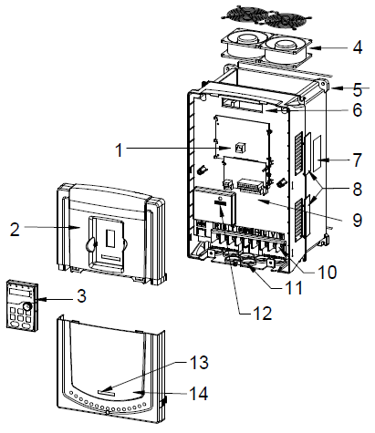
Fig 3-6 Structure diagram
Serial No. | Name | Illustration |
1 | Keypad interface | Connect the keypad |
2 | Upper cover plate | Protect the internal parts and components |
3 | Keypad | See Chapter 5 "Keypad operation procedures" for detailed information |
4 | Cooling fan | See Chapter 9 "Routine maintenance" for detailed information |
5 | Wiring interface | Connect to the control board and the drive board |
6 | Nameplate | See Chapter 3"Product overview"for detailed information |
7 | Ventilation hole cover plate | Optional. The ventilation hole cover plate will increase the protection level as well as the internal temperature of the VFD, which requiring the VFD to be used under derating. |
8 | Control terminals | See Chapter 4 "Installation guide"for detailed information |
9 | Main circuit terminals | See Chapter 4 "Installation guide"for detailed information |
10 | Main circuit cable inlet | Fix the main circuit cable |
11 | POWER light | Power indicator |
12 | Simple nameplate | See section 3.5 "Model code" for detailed information |
13 | Lower cover plate | Protect the internal parts and components |