4.2.1 Installation environment
The installation environment is the safeguard for a full performance and long-term stable functions of the VFD. Check the installation environment as followings:
Environment | Conditions |
Installation site | Indoor |
Environment temperature | -10–+50°C If the ambient temperature of the VFD is above 40°C, derate 1% for every additional 1°C. It is not recommended to use the VFD if the ambient temperature exceeds 50°C. In order to improve the reliability of the device, do not use the VFD if the ambient temperature changes frequently. Please provide cooling fan or air conditioner to control the internal ambient temperature below the required one if the VFD is used in a close space such as in the control cabinet. When the temperature is too low, if the VFD needs to restart to run after a long stop, it is necessary to provide an external heating device to increase the internal temperature, otherwise damage to the devices may occur. |
Humidity | RH ≤ 90%, no condensation is allowed. The max relative humility should be equal to or less than 60% in corrosive air. |
Storage temperature | -30–+60°C |
Running environment condition | Install the VFD on a site described as follows: Far away from electromagnetic radiation sources; Without oil mist, corrosive gas, flammable gas, or other contaminative air; Keeping foreign objects, such as metal power, dust, oil, and water, from dropping into the VFD (do not install it on the flammable materials such as wood); Without radioactive and flammable materials; Without harmful gas or liquid; With less salt spray; Without direct sunlight. |
Altitude | When the altitude exceeds 1000m but is lower than 3000m, derate 1% for every additional 100m; When the altitude exceeds 2000m, configure an isolation transformer on the input end of the VFD. When the altitude exceeds 3000m but is lower than 5000m, contact us for technical consultation. Do not use the VFD at an altitude higher than 5000m. |
Vibration | ≤ 5.88m/s2 (0.6g) |
Installation direction | The VFD should be installed in upright position to ensure sufficient cooling effect. |
Note:
1. Goodrive35 series VFDs should be installed in a clean and well ventilated environment according to enclosure classification.
2. Cooling air must be clean, free from corrosive materials and electrically conductive dust.
4.2.2 Installation direction
The VFD may be installed on the wall or in a cabinet.
The VFD must be installed in an upright position. Check the installation site according to the requirements below. Refer to Appendix C "Dimension drawings" for frame details.
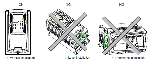
Figure 4‑1 Installation direction of the VFD
The VFD can be installed in three different ways, depending on the frame size:
a) Wall mounting (for the VFDs of 380 V≤315 kW and the VFDs of 660 V≤350 kW)
b) Flange mounting (for the VFDs of 380 V≤200 kW and the VFDs of 660 V≤220 kW)
c) Floor mounting (for the VFDs of 380 V 220-500 kW and the VFDs of 660 V 250–630 kW)
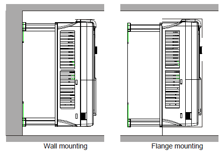
Figure 4‑2 Installation manner
(1) Mark the hole location. The location of the holes is shown in the Appendix C "Dimension drawings".
(2) Fix the screws or bolts to the marked locations.
(3) Put the VFD against the wall.
(4)Tighten the screws in the wall securely.
Note:
1. The flange installation of the VFDs of 380 V 1.5–30 kW need flange board, while the flange installation of the VFDs of 380 V 37–200 kW and 660 V 22–220 kW does not need.
2. The VFDs of 380 V 220–315 kW and 660 V 250–350 kW need optional bases and there is an input AC reactor (or DC reactor) and output AC reactor in the base.
4.2.4 Single installation
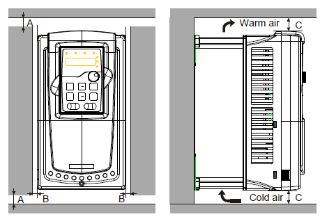
Figure 4‑3 Single installation
Note: The minimum space of B and C is 100mm.
4.2.5 Multiple installations
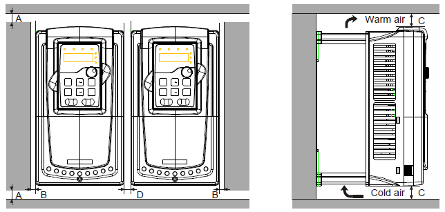
Figure 4‑4 Parallel installation
Note:
1. When installing VFDs with different sizes, align with the upper part of the VFD before installation for the convenience of future maintenance;
2. The minimum space of B, D and C is 100mm.
4.2.6 Vertical installation
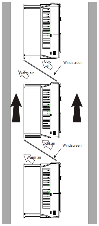
Figure 4‑5 Vertical installation
Note: Windscreen should be installed in vertical installation for avoiding mutual impact and insufficient cooling.
4.2.7 Tilt installation
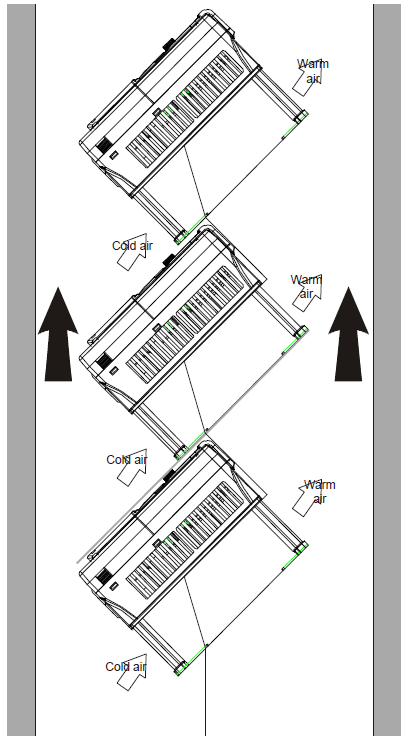
Figure 4‑6 Tilt installation
Note: Ensure the separation of the wind input and output channels in tilt installation for avoiding mutual impact.